
 Kia Sportage: Engine compartment fuse panel
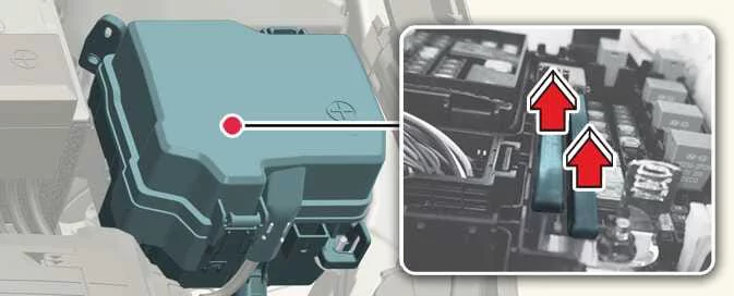 |
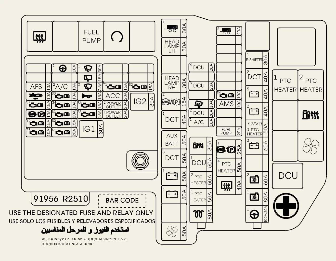
Engine Room Junction Block
|
Fuse name and symbol |
Fuse rating |
Protected circuit |
||
|---|---|---|---|---|
|
MULTI FUSE1 |
MDPS1 |
 |
80 A/100 A |
Motor Driven Power Steering Unit |
|
COOLING FAN1 |
 |
80 A |
Cooling Fan |
|
|
COOLING FAN2 |
 |
60 A |
Cooling Fan |
|
|
B+3 |
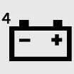 |
60 A |
PDC Junction Block (fuses: E-SHIFTER2, POWER TAILGATE, P/SEAT (DRV), P/SEAT (PASS), S/HEATER FRT, S/HEATER RR, SUNROOF1, MODULE11, P/WINDOW LH, P/WINDOW RH, MODULE8, TRAILER3, WIRELESS DCU, MODULE9) |
|
|
PTC HEATER3 |
 |
50 A |
PTC Heater Relay |
|
|
CVVD |
 |
50 A |
CVVD ACTR |
|
|
B+2 |
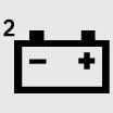 |
40 A |
PDC Junction Block (IPS8/IPS9/IPS10/IPS11/IPS12) |
|
|
B+5 |
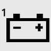 |
40 A |
PDC Junction Block (fuses: AMP, MODULE10, AIRBAG2, BATTERY MANAGEMENT1/2, ECS) |
|
|
DCT2 |
 |
40 A |
TCU (7DCT) |
|
|
E-SHIFTER1 |
 |
30 A |
SCU (System Control Unit) |
|
|
MULTI FUSE2 |
GLOW |
 |
80 A |
Glow Plug Control Unit |
|
PTC HEATER1 |
 |
50 A |
PTC Heater Relay |
|
|
PTC HEATER2 |
 |
50 A |
PTC Heater Relay |
|
|
DCU1 |
 |
50 A |
DCU Relay |
|
|
FUEL HEATER |
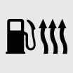 |
30 A |
FUEL HEATER Relay |
|
|
FUSE |
DCU4 |
 |
20 A |
Domain Control Unit |
|
DCU3 |
 |
20 A |
Domain Control Unit |
|
|
DCU2 |
 |
20 A |
Domain Control Unit |
|
|
A/C |
 |
10 A |
Aircon Control Unit |
|
|
BLOWER |
 |
50 A |
Blower Relay |
|
|
B+4 |
 |
50 A |
PDC Junction Block (fuses: MULTIMEDIA, MEMORY1, MEMORY2, CCU, BDC1, BRAKE SWITCH, SUNROOF2, 4WD, DOOR LOCK, TAILGATE OPEN) |
|
|
B+1 |
 |
50 A |
PDC Junction Block (IPS1/IPS2/IPS3/IPS4/IPS5/IPS6/IPS7) |
|
|
DCT3 |
 |
50 A |
SGA |
|
|
AUX BATT |
 |
50 A |
20AH Lithium Type Battery |
|
|
DCT1 |
 |
40 A |
TCU (7DCT) |
|
|
ABS2/EPB2 |
 |
15 A |
ESP (Electronic Stability Program Control Module) |
|
|
HEAD LAMP RH |
 |
30 A |
Front Head Lamp RH |
|
|
HEAD LAMP LH |
 |
30 A |
Front Head Lamp LH |
|
|
TRAILER1 |
 |
20 A |
Trailer CTM2 type (with e-brake) |
|
|
REAR HEATED |
 |
40 A |
Rear Heated Relay |
|
|
PTC HEATER4 |
 |
50 A |
PTC Heater Relay |
|
|
TRAILER2 |
 |
20 A |
Trailer CTM2 type (with e-brake) |
|
|
ABS1/EPB1 |
 |
25 A |
ESP (Electronic Stability Program Control Module) |
|
|
FUEL PUMP |
 |
20 A |
Fuel Pump Relay |
|
|
TRAILER2 |
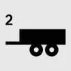 |
30 A |
Trailer (CTM2 Unit) |
|
PCB Block
|
Fuse name |
Symbol |
Fuse rating |
Protected circuit |
|---|---|---|---|
|
IG2 |
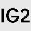 |
40 A |
IG2 Relay |
|
IG1 |
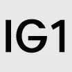 |
40 A |
IG1 Relay, ACC Relay |
|
FRT WIPER2 |
 |
7.5 A |
Front Wiper (Low) Relay, BDC (Body Domain Controller) |
|
ECU 4 |
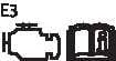 |
20 A |
Power train Control Module |
|
SENSOR1 |
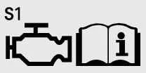 |
20 A |
Ignition Coil #1–#4 |
|
ECU 3 |
 |
10 A |
Power train Control Module |
|
SENSOR5 |
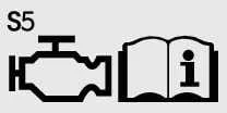 |
10 A |
Fuel Pump Relay |
|
TCU2 |
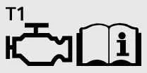 |
10 A |
Transmission Control Module |
|
TCU3 |
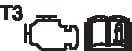 |
10 A |
Transaxle Range Switch |
|
SENSOR3 |
 |
20 A |
ECM (Engine Control Module) |
|
ECU1 |
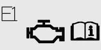 |
20 A |
Power train Control Module |
|
SENSOR2 |
 |
15 A |
Oxygen Sensor (Up/Down) |
|
FR WIPER1 |
 |
30 A |
Wiper Main Relay, Front Wiper (Low) Relay |
|
RR WIPER |
 |
15 A |
Wiper Main Relay, ICU Junction Block (Rear Wiper Relay) |
|
HORN |
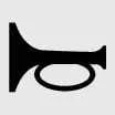 |
15 A |
Horn Relay |
|
B/ALARM HORN |
 |
15 A |
Burglar Alarm Horn Relay |
|
FCA |
 |
10 A |
Front Radar |
|
SENSOR4 |
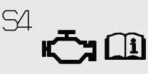 |
10 A |
Smartstream G2.0: Oil Control Valve #1/#2 (Intake/Exhaust), Variable Oil Pump Solenoid, Variable Intake Solenoid Valve, Purge Control Solenoid Valve, Cooling Fan Controller, Air Conditioner Compressor Relay, E/R Junction Block (Cooling Fan Relay High). Smartstream G2.5 T-GDi: Oil Control Valve #2 (Exhaust), Purge Control Solenoid Valve, Variable Oil Pump Solenoid, Variable Intake Solenoid Valve, Cooling Fan Controller, Air Conditioner Compressor Relay. |
|
SENSOR6 |
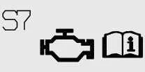 |
15 A |
Injector #1–#4 |
|
ECU2 |
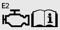 |
15 A |
Power train Control Module |
|
ECU6 |
 |
10 A |
Power train Control Module |
|
TCU1 |
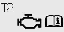 |
15 A |
Transmission Control Module |
|
ABS3/EPB3 |
 |
10 A |
ESP (Electronic Stability Program) Control Module |
|
POWER OUTLET2 |
 |
20 A |
Front Power Outlet |
|
POWER OUTLET1 |
 |
20 A |
Luggage Power Outlet |
MDPS (Motor Driven Power Steering) is also known as EPS (Electric Power Steering).
Relay
Use the table below to identify the relay types shown for the Kia Sportage engine compartment fuse panel.
|
Relay name |
Symbol |
Type |
|---|---|---|
|
Rear Heated Relay |
 |
MICRO |
|
Start Relay |
 |
MICRO |
|
Fuel Pump Relay |
 |
MICRO |
|
Cooling Fan Relay High |

|
MINI |
|
PTC Heater Relay #1 |

|
MICRO |
|
Fuel Filter Heating Relay |
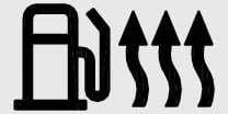
|
MICRO |
|
PTC Heater Relay #2 (Diesel) |
 |
MICRO |
|
Blower Relay |
 |
MICRO |
 Driver's side fuse panel
 Engine compartment fuse panel (Battery terminal cover)
See also:
Components and Components Location
Component (1)
1. Steering column shaft2. Lighting switch3. Wiper and washer switch4. Screw5. Clock spring
Component (2)
...
Components and Components Location
Components Location
1. Front axle2. Front lower arm3. Drive shaft4. Stabilizer bar5. Steering gearbox6. Sub frame7. Front strut assembly
...
Components and Components Location
Components Location
1. PCV valve2. Canister3. Purge control solenoid valve (PCSV)4. Fuel tank pressure sensor (FTPS)5. Canister close valve (CCV)6. Fuel level sensor (FLS)7. Fuel tank air filt ...
Categories
- Home
- Kia Sportage NQ5 (2022-2026) Owner's Manual
- Kia Sportage QL (2015-2019) Owner's Manual
- Kia Sportage QL (2015-2019) Service Manual
- Kia Sportage SL 2010-2016 Owner's Manual
- Kia Sportage SL 2010-2016 Service Manual
