 Kia Sportage: Crankshaft Position Sensor (CKPS): Repair procedures
Third generation SL (2010Ц2016) / Kia Sportage SL Service & Repair Manual / Engine Control / Fuel System / Engine Control System / Crankshaft Position Sensor (CKPS): Repair procedures
| Inspection |
| 1. |
Check the signal waveform of the CMPS and CKPS using the GDS.
|
| Removal |
| 1. |
Turn the ignition switch OFF and disconnect the battery negative (-) cable. |
| 2. |
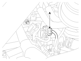
Disconnect the crankshaft position sensor connector (A).
|
| 3. |
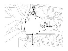
Remove the protector (A).
|
| 4. |
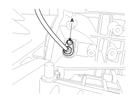
Remove the installation bolt (A), and then remove the crankshaft position sensor.
|
| Installation |
|
|
|
| 1. |
Installation is reverse of removal.
|
 Crankshaft Position Sensor (CKPS): Schematic Diagrams
Circuit Diagram
...
 Camshaft Position Sensor (CMPS): Description and Operation
Description
Camshaft Position Sensor (CMPS) is a hall sensor and detects the camshaft position by using a hall element.
It is related with Crankshaft Position Sensor (CKPS) and
detects the pisto ...
Other Information:
Intake Air Temperature Sensor (IATS): Repair procedures
Inspection
1.
Turn the ignition switch OFF.
2.
Disconnect the IATS connector.
3.
Measure resistance between the IATS terminals 3 and 4.
4.
Check that the resistance is within the speci ...
Direct Electro Hydraulic Actuator Coupling: Components and Components Location
Component Location
1. Automatic transaxle2. Transfer assembly3. Propeller shaft4. Coupling assembly5. Differential assembly
Components
1. Actuator2. Bleed valve3. Flange & Input shaft4. ...
Categories
- Home
- Kia Sportage QL (2015-2019) Owners Manual
- Kia Sportage QL (2015-2019) Service Manual
- Kia Sportage SL 2010-2016 Owners Manual
- Kia Sportage SL 2010-2016 Service Manual
Copyright © www.kispmanual.com 2014-2024


