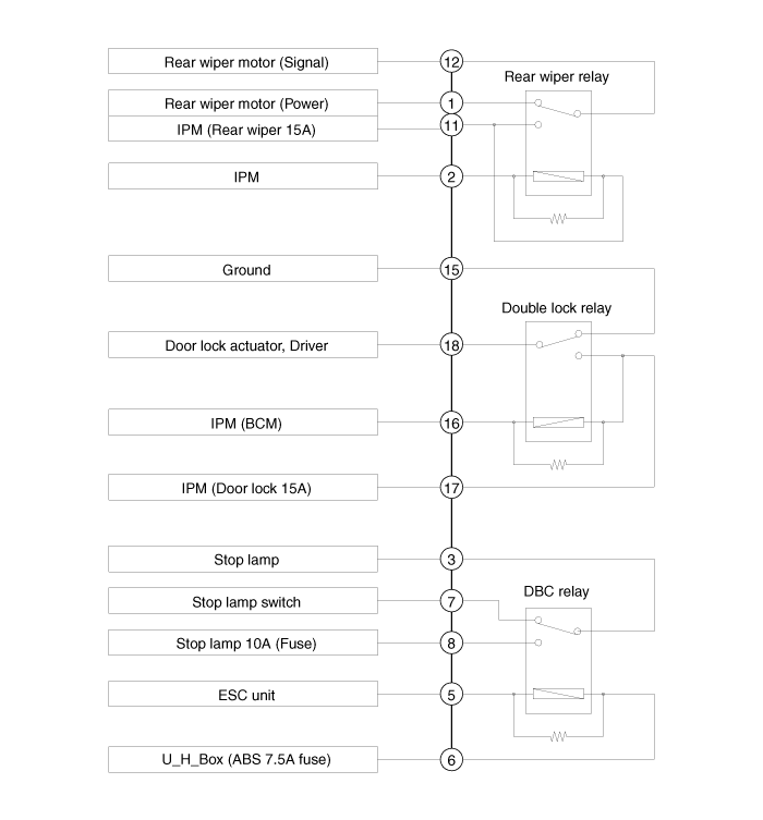
 Kia Sportage: ICM (Integrated Circuit Module) Relay Box: Schematic Diagrams
Third generation SL (2010Ц2016) / Kia Sportage SL Service & Repair Manual / Body Electrical System / Fuses And Relays / ICM (Integrated Circuit Module) Relay Box: Schematic Diagrams
| Schematic Diagram |

 ICM (Integrated Circuit Module) Relay Box: Components and Components Location
Component
Pin Information
NoConnector ANoConnector A1Rear wiper motor (Power)11IPM (Rear wiper 15A)2IPM12Rear wiper motor (Signal)3Stop lamp13-4-14-5ESC unit15GND6U_H_Box (ABS 7.5A fuse)16IPM (B ...
 ICM (Integrated Circuit Module) Relay Box: Description and Operation
Description
The ICM relay (A) is united with rear wiper relay, and DBC relay which installed inside the lower crash pad. ...
Other Information:
4WD ECU: Schematic Diagrams
Circuit Diagram
4WD ECU Connector
PinFunction1Oil pressure motor A2Oil pressure motor B3Lock mode switch4-5Input sensor signal(+)6-7CAN communication line (High)8CAN communication line (Low)9- ...
Rear Door: Repair procedures
Replacement
Door Trim Replacement
Х
Take care not to scratch the door trim and other parts.
Х
Put on gloves to protect your hands.
1.
Using a sc ...
Categories
- Home
- Kia Sportage QL (2015-2019) Owners Manual
- Kia Sportage QL (2015-2019) Service Manual
- Kia Sportage SL 2010-2016 Owners Manual
- Kia Sportage SL 2010-2016 Service Manual
Copyright © www.kispmanual.com 2014-2024
