 Kia Sportage: Cruise Control Switch: Repair procedures
Third generation SL (2010–2016) / Kia Sportage SL Service & Repair Manual / Engine Electrical System / Cruise Control System / Cruise Control Switch: Repair procedures
| Removal and Installation |
| 1. |
Disconnect the battery (-) terminal.
|
| 2. |
Remove the air-bag module from the steering wheel. ( Refer to RT group) |
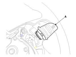
| 3. |
Remove the steering wheel. (Refer to ST group) |
| 4. |
Remove the cruise control switch (A) after unfastening the 2 screws and disconnecting the switch connector.
|
| 5. |
Installation is reverse order of removal. |
| Inspection |
Measuring Resistance
| 1. |
Disconnect the cruise control switch connector from the control switch.
|
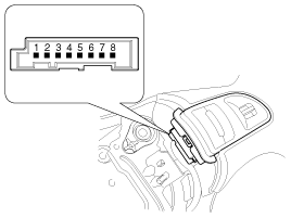
| 2. |
Measure resistance between terminals on the control switch when each function switch is ON (switch is depressed).
|
| 3. |
If not within specification, replace switch. |
Measuring Voltage
| 1. |
Connect the cruise control switch connector to the control switch. |
| 2. |
Measure voltage between terminals on the harness side connector when each function switch is ON (switch is depressed).
|
| 3. |
If not within specification, inspect the control switch resistance.
The measuring resistance value is not within specification, replace the switch and measure the voltage again. |
| 4. |
If resistance is OK but, measuring voltage is not within
specification, inspect the wiring harness and connectors between the
switch and the ECM. |
 Cruise Control Switch: Schematic Diagrams
Circuit Diagram
...

Other Information:
Instrument Cluster: Schematic Diagrams
Circuit Diagram (1)
Circuit Diagram (2)
CLU1 message signal flow (B > C CAN gateway)
CLU2 message signal flow (B > C CAN gateway)
CLU message 1 signal flow (C > B CAN gateway)
CLU message 3 signa ...
Vanity mirror lamp
: The lamp will turn on if this
button is pressed.
: The lamp will turn off if this
button is pressed.
✽ NOTICE
Turn off the lamp before return the sunvisor to its original position. ...
Categories
- Home
- Kia Sportage QL (2015-2019) Owners Manual
- Kia Sportage QL (2015-2019) Service Manual
- Kia Sportage SL 2010-2016 Owners Manual
- Kia Sportage SL 2010-2016 Service Manual
Copyright © www.kispmanual.com 2014-2024