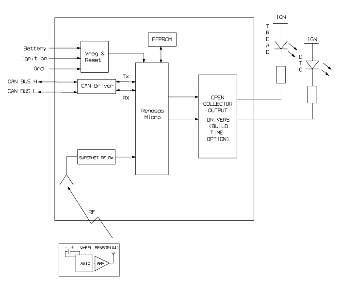
 Kia Sportage: TPMS Receiver: Schematic Diagrams
Third generation SL (2010Ц2016) / Kia Sportage SL Service & Repair Manual / Suspension System / Tire Pressure Monitoring System / TPMS Receiver: Schematic Diagrams
| Schematic Diagrams |
| TPMS Receiver Circuit Diagram |

| Harness Connector |

| Pin | Description |
| 1 | Battery |
| 2 | CAN_High |
| 3 | GND |
| 4 | - |
| 5 | - |
| 6 | - |
| 7 | IGN |
| 8 | CAN_Low |
| 9 | - |
| 10 | - |
| 11 | - |
| 12 | - |
 TPMS Receiver: Description and Operation
Description
1.
Mode
(1)
Virgin State
Х
The receiver as a sole part is shipped in this state. Replacement parts should therefore arrive in this state.
Х
In this state, there is ...
 TPMS Receiver: Repair procedures
Replacement
When the receiver first arrives for replacement:
a.
It will be in Virgin State.
b.
It will not be configured for any specific platform.
c.
It will ...
Other Information:
Immobilizer Control Unit: Repair procedures
Removal
1.
Disconnect the negative (-) battery terminal.
2.
Remove the crash pad lower panel.
(Refer to the BD group - "Crash pad")
3.
Remove the steering column assembly.
(Refer to the ...
Push-starting
Vehicles equipped with automatic transaxle and manual transaxle vehicles equipped
with clutch lock system cannot be push-started.
Follow the directions in this section for jump-starting.
WARNI ...
Categories
- Home
- Kia Sportage QL (2015-2019) Owners Manual
- Kia Sportage QL (2015-2019) Service Manual
- Kia Sportage SL 2010-2016 Owners Manual
- Kia Sportage SL 2010-2016 Service Manual
Copyright © www.kispmanual.com 2014-2024
