
 Kia Sportage: Brake Pedal: Repair procedures
Third generation SL (2010–2016) / Kia Sportage SL Service & Repair Manual / Brake System / Brake System / Brake Pedal: Repair procedures
| Removal |
| 1. |
Remove the crash pad lower panel and reinforcement panel. (Refer to the Body group- crash pad). |
| 2. |
Pull down steering column shaft after removing bolts and nuts. |
| 3. |
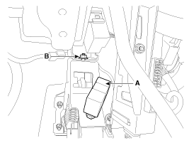
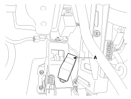
Disconnect the stop lamp switch connector (A).
|
| 4. |
Remove the brake pedal member mounting nut (B).
|
| 5. |
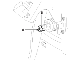
Remove the snap pin (A) and clevis pin (B).
|
| 6. |
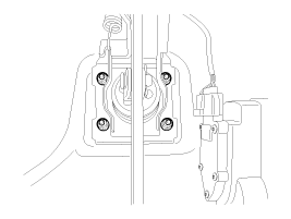
Remove the brake pedal member assembly mounting nuts and then remove the brake pedal assembly.
|
| 7. |
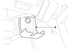
Remove the cowl bracket (A).
|
| Inspection |
| 1. |
Check the bushing for wear. |
| 2. |
Check the brake pedal for bending or twisting. |
| 3. |
Check the brake pedal return spring for damage. |
| 4. |
Check the stop lamp switch.
|
| Installation |
| 1. |
Installation is the reverse of removal.
|

| 2. |
Adjust the brake pedal height and free play. |
| 3. |
Check the brake pedal operation. |
| Adjustment |
| Brake Pedal Height and Free Play |
| 1. |
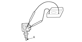
Disconnect the stop lamp switch connector (A) and loosen the stop lamp switch lock nut.
|
| 2. |
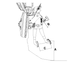
Adjust the brake pedal height (A) as illustration below.
|
| 3. |
Adjust the stop lamp switch clearance (B) and brake pedal free play.
|
| 4. |
Connect the stop lamp switch connector. |
 Brake Pedal: Components and Components Location
Components
1. Cowl bracket2. Brake pedal member assembly3. Stop lamp switch4. Return spring5. Brake pedal stopper6. Clevis pin7. Snap pin8. Brake pedal
...
 Front Disc Brake: Components and Components Location
Components
1. Guide rod bolt2. Bleed screw3. Caliper bracket 4. Caliper body5. Inner pad shim6. Brake pad7. Pad retainer
...
Other Information:
LCD display warning
Key not in vehicle
If the smart key is not in the vehicle and if any door is opened or closed with
the ENGINE START/STOP button in the ACC, ON, or START position, the warning illuminates
on the L ...
Accelerator Position Sensor (APS): Repair procedures
Inspection
1.
Connect the GDS on the Data Link Connector (DLC).
2.
Turn the ignition switch ON.
3.
Measure the output voltage of the APS 1 and 2 at C.T and W.O.T.
Specification: Refer t ...
Categories
- Home
- Kia Sportage QL (2015-2019) Owners Manual
- Kia Sportage QL (2015-2019) Service Manual
- Kia Sportage SL 2010-2016 Owners Manual
- Kia Sportage SL 2010-2016 Service Manual

Copyright © www.kispmanual.com 2014-2026