 Kia Sportage: Crash Pad: Repair procedures
Third generation SL (2010ŌĆō2016) / Kia Sportage SL Service & Repair Manual / Body (Interior and Exterior) / Interior / Crash Pad: Repair procedures
| Replacement |
Cluster Replacement
|
| 1. |
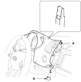
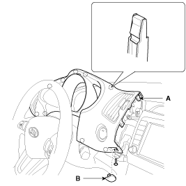
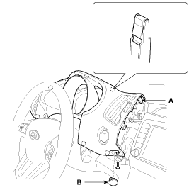
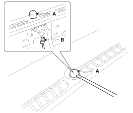
Remove the cluster fascia panel cap (B) and then loosening the mounting screw. |
| 2. |
Using a screwdriver or remover, remove the cluster fascia panel (A).
|
| 3. |
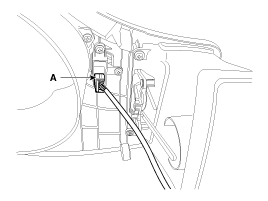
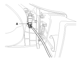
Disconnect the connector (A).
|
| 4. |
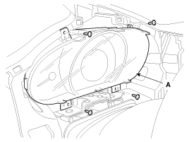
After loosening the mounting screws, then remove the cluster assembly (A).
|
| 5. |
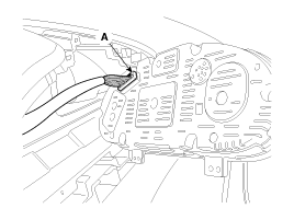
Disconnect the connector (A).
|
| 6. |
Installation is the reverse of removal.
|
Center Facia Panel Replacement
|
| 1. |
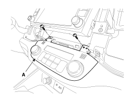
Remove the cluster fascia panel cap (B) and then loosening the mounting screw. |
| 2. |
Using a screwdriver or remover, remove the cluster fascia panel (A).
|
| 3. |
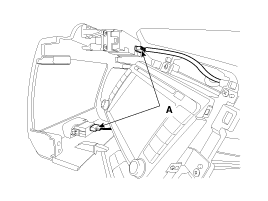
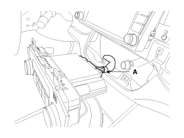
Disconnect the connector (A).
|
| 4. |
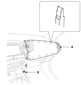
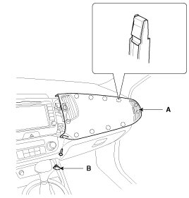
Remove the crash pad garnish cap (B) and then loosening the mounting screw. |
| 5. |
Using a screwdriver or remover, remove the crash pad garnish (A).
|
| 6. |
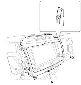
After loosening the mounting screws, then remove the center facia panel (A).
|
| 7. |
Disconnect the connectors (A).
|
| 8. |
Installation is the reverse of removal.
|
Crash Pad Lower Panel Replacement
|
| 1. |
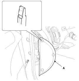
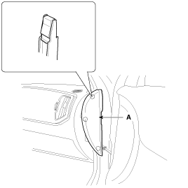
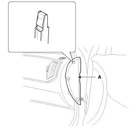
Using a screwdriver or remover, remove the crash pad side cover (A).
|
| 2. |
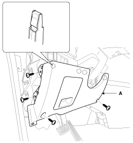
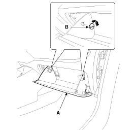
After loosening the mounting screws, then remove the crash pad lower panel (A).
|
| 3. |
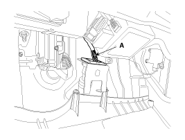
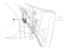
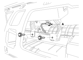
Disconnect the diagnosis connector (A).
|
| 4. |
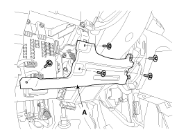
After loosening the mounting bolts, then remove reinforcing panel (A).
|
| 5. |
Installation is the reverse of removal.
|
Audio assembly Replacement
|
| 1. |
Remove the cluster fascia panel cap (B) and then loosening the mounting screw. |
| 2. |
Using a screwdriver or remover, remove the cluster fascia panel (A).
|
| 3. |
Disconnect the connector (A).
|
| 4. |
Remove the crash pad garnish cap (B) and then loosening the mounting screw. |
| 5. |
Using a screwdriver or remover, remove the crash pad garnish (A).
|
| 6. |
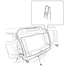
After loosening the mounting screws, then remove the center facia panel (A).
|
| 7. |
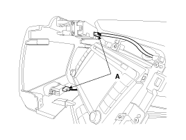
Disconnect the connectors (A).
|
| 8. |
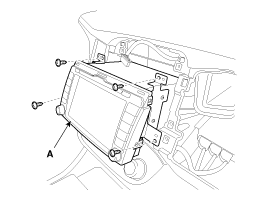
After loosening the mounting screws, then remove the audio assembly (A).
|
| 9. |
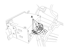
Disconnect the connectors (A).
|
| 10. |
Installation is the reverse of removal.
|
Heater Control Unit Replacement
|
| 1. |
Remove the cluster fascia panel cap (B) and then loosening the mounting screw. |
| 2. |
Using a screwdriver or remover, remove the cluster fascia panel (A).
|
| 3. |
Disconnect the connector (A).
|
| 4. |
Remove the crash pad garnish cap (B) and then loosening the mounting screw. |
| 5. |
Using a screwdriver or remover, remove the crash pad garnish (A).
|
| 6. |
After loosening the mounting screws, then remove the center facia panel (A).
|
| 7. |
Disconnect the connectors (A).
|
| 8. |
After loosening the mounting screws, then remove the heater control unit (A).
|
| 9. |
Disconnect the connector (A).
|
| 10. |
Installation is the reverse of removal.
|
Glove Box Replacement
|
| 1. |
Using a screwdriver or remover, remove the crash pad side cover (A).
|
| 2. |
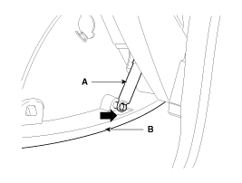
Disconnect the guide (B) from the glove box (A).
|
| 3. |
Disconnect the life (A) from the glove box (B).
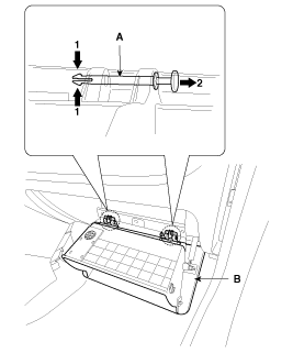
|
| 4. |
Disconnect the pin (A) and then remove the glove box (B).
|
| 5. |
Installation is the reverse of removal.
|
Shroud Replacement
| 1. |
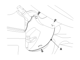
After loosening the mounting screws, then remove the shroud assembly (A).
|
| 2. |
Installation is the reverse of removal. |
Crash Pad Side Cover Replacement
|
| 1. |
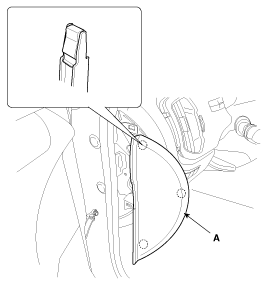
Using a screwdriver or remover, remove the crash pad side cover (A).
[Driver''s]
[Passenger''s]
|
| 2. |
Installation is the reverse the removal. |
Main Crash Pad Replacement
|
| 1. |
Remove the following items.
|
| 2. |
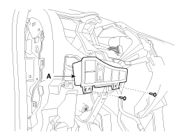
After loosening the mounting screws, then remove the crash pad switch assembly (A).
|
| 3. |
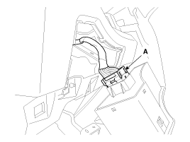
Disconnect the connector (A).
|
| 4. |
Disconnect the passenger`s airbag connector (A). |
| 5. |
Loosen the mounting bolts.
|
| 6. |
Using a screwdriver, remove the photo sensor (A). |
| 7. |
Disconnect the photo sensor connector (B).
|
| 8. |
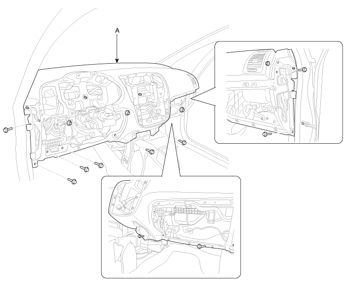
After loosening the mounting bolts and nuts, then remove the main crash pad assembly (A).
|
| 9. |
Installation is the reverse of removal.
|
Cowl Cross Bar Replacement
|
| 1. |
Remove the following items.
|
| 2. |
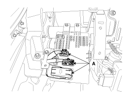
Disconnect the blower unit connectors.
(Refer to the HA group - "Air conditioning system, Heater, Blower") |
| 3. |
Disconnect the wiring connectors. |
| 4. |
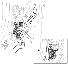
Using a screwdriver or remover, remove the multi box (A).
[Driver''s]
|
| 5. |
Disconnect the wiring connectors. |
| 6. |
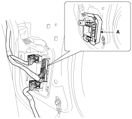
Using a screwdriver or remover, remove the multi box (A).
[Passenger''s]
|
| 7. |
Disconnect the connectors (A).
|
| 8. |
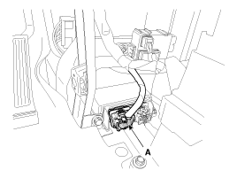
Disconnect the airbag control module (SRSCM) connector (A).
|
| 9. |
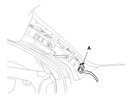
Disconnect the connector (A) and the mounting clips in the driver''s front pillar.
|
| 10. |
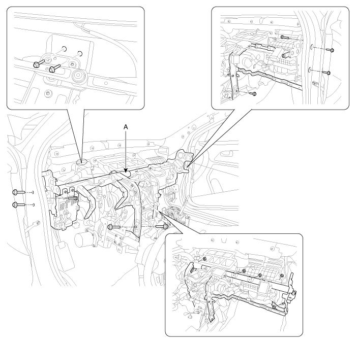
After loosening the mounting bolts and nuts, then remove the cowl cross bar (A).
|
| 11. |
Installation is the reverse of removal.
|
 Crash Pad: Components and Components Location
Components
1. Main crash pad assembly2. Crash pad side cover [LH]3. Crash pad side cover [RH]4. Cluster fascia panel5. Reinforcing panel6. Crash pad lower panel7. Center facia panel8. Crash pad g ...
 Roof Trim: Components and Components Location
Components
1. Roof trim2. Sunvisor [Driver''s]3. Sunvisor [Passenger''s]
Components [Panoramaroof]
1. Roof trim2. Sunvisor [Driver''s]3. Sunvisor [Passenger''s]
...
Other Information:
1. Crankcase emission control system
The positive crankcase ventilation system is employed to prevent air pollution
caused by blow-by gases being emitted from the crankcase. This system supplies fresh
filtered air to the crankcase th ...
To decrease the cruising speed
Follow either of these procedures:
Push the - SET switch and hold it. Your vehicle will gradually slow down.
Release the switch at the speed you want to maintain.
Push the - SET switch and ...
Categories
- Home
- Kia Sportage QL (2015-2019) Owners Manual
- Kia Sportage QL (2015-2019) Service Manual
- Kia Sportage SL 2010-2016 Owners Manual
- Kia Sportage SL 2010-2016 Service Manual
Copyright ® www.kispmanual.com 2014-2026


