 Kia Sportage: Engine Control Module (ECM): Schematic Diagrams
Third generation SL (2010ŌĆō2016) / Kia Sportage SL Service & Repair Manual / Engine Control / Fuel System / Engine Control System / Engine Control Module (ECM): Schematic Diagrams
| ECM Terminal And Input/Output signal |

| ECM Terminal Function |
Connector [CHTG-AG]
| Pin No. | Description | Connected to |
| 1 | Ignition Coil (Cylinder #2) control output [Without Smart Key] | Ignition Coil (Cylinder #2) |
| Ignition Coil (Cylinder #3) control output [Smart Key] | Ignition Coil (Cylinder #3) | |
| 2 | - | |
| 3 | - | |
| 4 | - | |
| 5 | ETC Motor [+] control output | ETC Motor |
| 6 | ETC Motor [-] control output | ETC Motor |
| 7 | - | |
| 8 | - | |
| 9 | - | |
| 10 | - | |
| 11 | - | |
| 12 | Sensor power (+5V) | Electric Waste Gate Actuator (EWGA) |
| Rail Pressure Sensor (RPS) | ||
| A/C Pressure Transducer (APT) | ||
| Manifold Absolute Pressure Sensor (MAPS) #2 | ||
| Fuel Tank Pressure Sensor (FTPS) | ||
| 13 | - | |
| 14 | Heated Oxygen Sensor (HO2S) [Bank 1/Sensor 2] signal input | Heated Oxygen Sensor (HO2S) [Bank 1/Sensor 2] |
| 15 | - | |
| 16 | Electric Waste Gate Actuator (EWGA) Feed beck signal | Electric Waste Gate Actuator (EWGA) |
| 17 | CVVT Oil Temperature Sensor (OTS) signal input | CVVT Oil Temperature Sensor (OTS) |
| 18 | Manifold Absolute Pressure Sensor (MAPS)#2 signal input | Manifold Absolute Pressure Sensor (MAPS)#2 |
| 19 | - | |
| 20 | Fuel Tank Pressure Sensor (FTPS) signal input | Fuel Tank Pressure Sensor (FTPS) |
| 21 | Electric Waste Gate Actuator (EWGA) DC Motor output (-) | Electric Waste Gate Actuator (EWGA) |
| 22 | Ignition Coil (Cylinder #4) control output [Without Smart Key] | Ignition Coil (Cylinder #4) |
| Ignition Coil (Cylinder #1) control output [Smart Key] | Ignition Coil (Cylinder #1) | |
| 23 | - | |
| 24 | - | |
| 25 | - | |
| 26 | - | |
| 27 | - | |
| 28 | - | |
| 29 | - | |
| 30 | - | |
| 31 | - | |
| 32 | - | |
| 33 | Sensor power (+5V) | Throttle Position Sensor (TPS) 1,2 |
| 34 | - | |
| 35 | Sensor ground | Heated Oxygen Sensor (HO2S) [Bank 1/Sensor 2] |
| 36 | - | |
| 37 | Sensor ground | Electric Waste Gate Actuator (EWGA) |
| 38 | - | |
| 39 | Rail Pressure Sensor (RPS) signal input | Rail Pressure Sensor (RPS) |
| 40 | - | |
| 41 | Sensor ground | Fuel Tank Pressure Sensor (FTPS) |
| 42 | Electric Waste Gate Actuator (EWGA) DC Motor output (+) | Electric Waste Gate Actuator (EWGA) |
| 43 | - | |
| 44 | - | |
| 45 | - | |
| 46 | - | |
| 47 | - | |
| 48 | - | |
| 49 | - | |
| 50 | - | |
| 51 | - | |
| 52 | - | |
| 53 | - | |
| 54 | Sensor ground | Throttle Position Sensor (TPS) 1,2 |
| 55 | Sensor ground | Accelerator Position Sensor (APS) 2 |
| 56 | Sensor ground | Accelerator Position Sensor (APS) 1 |
| 57 | Immobilizer communication line | Smart Key Control Module [Smart Key] |
| Immobilizer Control Module [Immobilizer] | ||
| 58 | Sensor ground | CVVT Oil Temperature Sensor (OTS) |
| 59 | Intake Air Temperature Sensor (IATS) signal input | Intake Air Temperature Sensor (IATS) |
| 60 | Sensor ground | Rail Pressure Sensor (RPS) |
| 61 | Sensor ground | Manifold Absolute Pressure Sensor (MAPS) |
| Intake Air Temperature Sensor (IATS) | ||
| 62 | Sensor ground | Engine Coolant Temperature Sensor (ECTS) |
| 63 | Engine Coolant Temperature Sensor (ECTS) signal input | Engine Coolant Temperature Sensor (ECTS) |
| 64 | Ignition Coil (Cylinder #3) control output [Without Smart Key] | Ignition Coil (Cylinder #3) |
| Ignition Coil (Cylinder #2) control output [Smart Key] | Ignition Coil (Cylinder #2) | |
| 65 | - | |
| 66 | - | |
| 67 | - | |
| 68 | - | |
| 69 | - | |
| 70 | - | |
| 71 | - | |
| 72 | - | |
| 73 | - | |
| 74 | - | |
| 75 | Throttle Position Sensor (TPS) 2 signal input | Throttle Position Sensor (TPS) 2 |
| 76 | Accelerator Position Sensor (APS) 2 signal input | Accelerator Position Sensor (APS) 2 |
| 77 | Accelerator Position Sensor (APS) 1 signal input | Accelerator Position Sensor (APS) 1 |
| 78 | - | |
| 79 | - | |
| 80 | Sensor ground | A/C Pressure Transducer (APT) |
| 81 | Sensor ground | Manifold Absolute Pressure Sensor (MAPS) #2 |
| 82 | Manifold Absolute Pressure Sensor (MAPS) signal input | Manifold Absolute Pressure Sensor (MAPS) |
| 83 | Rc/Rp (Pump Cell Voltage) | Heated Oxygen Sensor [Bank 1/Sensor 1] |
| 84 | VS-/IP- (Common Ground for VS, IP) | Heated Oxygen Sensor [Bank 1/Sensor 1] |
| 85 | Ignition Coil (Cylinder #1) control output [Without Smart Key] | Ignition Coil (Cylinder #1) |
| Ignition Coil (Cylinder #4) control output [With Smart Key] | Ignition Coil (Cylinder #4) | |
| 86 | - | |
| 87 | - | |
| 88 | - | |
| 89 | - | |
| 90 | - | |
| 91 | - | |
| 92 | - | |
| 93 | - | |
| 94 | - | |
| 95 | - | |
| 96 | Throttle Position Sensor (TPS) 1 signal input | Throttle Position Sensor (TPS) 1 |
| 97 | Sensor power (+5V) | Accelerator Position Sensor (APS) 2 |
| 98 | Sensor power (+5V) | Accelerator Position Sensor (APS) 1 |
| 99 | - | |
| 100 | - | |
| 101 | A/C Pressure Transducer (APT) signal input | A/C Pressure Transducer (APT) |
| 102 | - | |
| 103 | Sensor power (+5V) | Manifold Absolute Pressure Sensor (MAPS) |
| 104 | Rc (Compensative Resistance) | Heated Oxygen Sensor [Bank 1/Sensor 1] |
| 105 | VS+ (NERNST Cell Voltage) | Heated Oxygen Sensor [Bank 1/Sensor 1] |
Connector [CHTG-BG]
| Pin No. | Description | Connected to |
| 1 | ECM ground | Chassis ground |
| 2 | ECM ground | Chassis ground |
| 3 | Battery power (B+) | Main Relay |
| 4 | ECM ground | Chassis ground |
| 5 | Battery power (B+) | Main Relay |
| 6 | Battery power (B+) | Main Relay |
| 7 | - | |
| 8 | Crankshaft Position Sensor (CKPS) signal input | Crankshaft Position Sensor (CKPS) |
| 9 | - | |
| 10 | Brake Switch 2 signal input | Brake Switch |
| 11 | - | |
| 12 | - | |
| 13 | - | |
| 14 | Electrical load [wiper] signal input | Wiper Relay |
| 15 | Electrical load signal input (FR) | Alternator |
| 16 | Alternator PWM signal output (COM) | Alternator |
| 17 | - | |
| 18 | Cooling Fan Relay [High] control output | Cooling Fan Relay [High] |
| 19 | Immobilizer Lamp control output | Immobilizer Lamp [Without Button Engine Start System] |
| 20 | - | |
| 21 | - | |
| 22 | Injector (Cylinder #2) [High] control output | Injector (Cylinder #2) |
| 23 | Injector (Cylinder #2) [Low] control output | Injector (Cylinder #2) |
| 24 | - | |
| 25 | Sensor ground | Crankshaft Position Sensor (CKPS) |
| 26 | - | |
| 27 | Brake Switch 1 signal input | Brake Switch |
| 28 | - | |
| 29 | Camshaft Position Sensor (CMPS) [Bank 1/Intake] signal input | Camshaft Position Sensor (CMPS) [Bank 1/Intake] |
| 30 | Camshaft Position Sensor (CMPS) [Bank 1/Exhaust] signal input | Camshaft Position Sensor (CMPS) [Bank 1/Exhaust] |
| 31 | - | |
| 32 | LIN communication signal input | Battery Sensor |
| 33 | Cooling Fan Relay [Low] control output | Cooling Fan Relay [Low] |
| 34 | - | |
| 35 | - | |
| 36 | - | |
| 37 | - | |
| 38 | - | |
| 39 | Injector (Cylinder #3) [High] control output | Injector (Cylinder #3) |
| 40 | Injector (Cylinder #3) [Low] control output | Injector (Cylinder #3) |
| 41 | Battery power (B+) | Ignition Switch |
| 42 | - | |
| 43 | - | |
| 44 | Sensor shield | Knock Sensor (KS) |
| 45 | Sensor ground | Knock Sensor (KS) |
| 46 | Sensor ground | Camshaft Position Sensor (CMPS) [Bank 1/Intake] |
| 47 | Sensor ground | Camshaft Position Sensor (CMPS) [Bank 1/Exhaust] |
| 48 | - | |
| 49 | - | |
| 50 | - | |
| 51 | - | |
| 52 | - | |
| 53 | Main Relay control output | Main Relay |
| 54 | - | |
| 55 | - | |
| 56 | Injector (Cylinder #4) [High] control output | Injector (Cylinder #4) |
| 57 | Injector (Cylinder #4) [Low] control output | Injector (Cylinder #4) |
| 58 | Battery power (B+) | Battery |
| 59 | - | |
| 60 | CAN [Low] | Other control module, Data Link Connector (DLC), Multi-Purpose Check Connector |
| 61 | - | |
| 62 | Knock Sensor (KS) signal input | Knock Sensor (KS) |
| 63 | Clutch Switch signal input | Clutch Switch [M/T] |
| 64 | - | |
| 65 | - | |
| 66 | - | |
| 67 | - | |
| 68 | - | |
| 69 | Starter Relay control output | Starter Relay [With Smart Key] |
| 70 | Fuel Pump Relay control output | Fuel Pump Relay |
| 71 | Engine speed signal output | Smart Key Control Module |
| 72 | RCV Control Solenoid Valve control output | RCV Control Solenoid Valve |
| 73 | Injector (Cylinder #1) [High] control output | Injector (Cylinder #1) |
| 74 | Injector (Cylinder #1) [Low] control output | Injector (Cylinder #1) |
| 75 | Battery power (B+) | Battery |
| 76 | - | |
| 77 | CAN [High] | Other control module, Data Link Connector (DLC), Multi-Purpose Check Connector |
| 78 | Vehicle speed signal input | ESC Control Unit [With ESC] |
| 79 | - | |
| 80 | - | |
| 81 | - | |
| 82 | Starter Control Switch signal input | Smart Key Control Module [With Smart Key] |
| 83 | Fuel Level Sender (FLS) signal input | Fuel Level Sender (FLS) |
| 84 | CVVT Oil Control Valve (OCV) [Bank 1/Exhaust] control output | CVVT Oil Control Valve (OCV) [Bank 1/Exhaust] |
| 85 | CVVT Oil Control Valve (OCV) [Bank 1/Intake] control output | CVVT Oil Control Valve (OCV) [Bank 1/Intake] |
| 86 | Purge Control Solenoid Valve (PCSV) control output | Purge Control Solenoid Valve (PCSV) |
| 87 | Canister Close Valve (CCV) control output | Canister Close Valve (CCV) |
| 88 | Heated Oxygen Sensor (HO2S) [Bank 1/Sensor 1] Heater control output | Heated Oxygen Sensor (HO2S) [Bank 1/Sensor 1] |
| 89 | Heated Oxygen Sensor (HO2S) [Bank 1/Sensor 2] Heater control output | Heated Oxygen Sensor (HO2S) [Bank 1/Sensor 2] |
| 90 | Fuel Pressure Regulator Valve [High] control output | Fuel Pressure Regulator Valve |
| 91 | Fuel Pressure Regulator Valve [Low] control output | Fuel Pressure Regulator Valve |
| ECM Terminal Input/ Output signal |
Connector [CHTG-AG]
| Pin No. | Description | Condition | Type | Level |
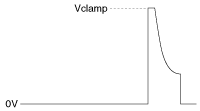
| 1 | Ignition Coil (Cylinder #2) control output [Without Smart Key] | Engine Running | Pulse | Vpeak = 360 ~ 440V |
| Ignition Coil (Cylinder #3) control output [With Smart Key] | 125 (333Hz at idle) | |||
| 2 | - | | | |
| 3 | - | | | |
| 4 | - | | | |
| 5 | ETC Motor [+] control output | Engine Running | Pulse | High: Battery Voltage |
| Low: Max.1.0V | ||||
| 6 | ETC Motor [-] control output | Engine Running | Pulse | High: Battery Voltage |
| Low: Max.1.0V | ||||
| 7 | - | | | |
| 8 | - | | | |
| 9 | - | | | |
| 10 | - | | | |
| 11 | - | | | |
| 12 | Sensor power (+5V) | IG OFF | DC | Max. 0.5V |
| IG ON | 4.75 ~ 5.25V | |||
| 13 | - | | | |
| 14 | Heated Oxygen Sensor (HO2S) [Bank 1/Sensor 2] signal input | Idle | DC | Rich : 0.6 ~ 1.0V |
| Lean : Max 0.4V | ||||
| 15 | - | | | |
| 16 | Electric Waste Gate Actuator (EWGA) Feed beck signal | | | |
| 17 | CVVT Oil Temperature Sensor (OTS) signal input | | | |
| 18 | Manifold Absolute Pressure Sensor (MAPS)#2 signal input | | | |
| 19 | - | | | |
| 20 | Fuel Tank Pressure Sensor (FTPS) signal input | Idle | Analog | -0.3 ~ 5.2V |
| 21 | Electric Waste Gate Actuator (EWGA) DC Motor output (-) | | | |
| 22 | Ignition Coil (Cylinder #4) control output [Without Smart Key] | Engine Running | Pulse | Vpeak = 360 ~ 440V |
| Ignition Coil (Cylinder #1) control output [With Smart Key] | 125 (333Hz at idle) | |||
| 23 | - | | | |
| 24 | - | | | |
| 25 | - | | | |
| 26 | - | | | |
| 27 | - | | | |
| 28 | - | | | |
| 29 | - | | | |
| 30 | - | | | |
| 31 | - | | | |
| 32 | - | | | |
| 33 | Sensor power (+5V) | IG OFF | DC | Max. 0.5V |
| IG ON | 4.75 ~ 5.25V | |||
| 34 | - | | | |
| 35 | Sensor ground | Idle | DC | -0.3 ~ 0.5V |
| 36 | - | |||
| 37 | Sensor ground | | | |
| 38 | - | | | |
| 39 | Rail Pressure Sensor (RPS) signal input | Idle | Analog | -0.3 ~ 5.2V |
| 40 | - | | | |
| 41 | Sensor ground | Idle | DC | -0.3 ~ 0.5V |
| 42 | Electric Waste Gate Actuator (EWGA) DC Motor output (+) | | | |
| 43 | - | |||
| 44 | - | | | |
| 45 | - | | | |
| 46 | - | | | |
| 47 | - | | | |
| 48 | - | | | |
| 49 | - | | | |
| 50 | - | | | |
| 51 | - | | | |
| 52 | - | | | |
| 53 | - | | | |
| 54 | Sensor ground | Idle | DC | -0.3 ~ 0.5V |
| 55 | Sensor ground | Idle | DC | -0.3 ~ 0.5V |
| 56 | Sensor ground | Idle | DC | -0.3 ~ 0.5V |
| 57 | Immobilizer communication line | | | |
| 58 | Sensor ground | | | |
| 59 | Intake Air Temperature Sensor (IATS) signal input | Idle | Analog | 0 ~ 5.0V (2.55V at Idle) |
| 60 | Sensor ground | Idle | DC | -0.3 ~ 0.5V |
| 61 | Sensor ground | Idle | DC | -0.3 ~ 0.5V |
| 62 | Sensor ground | Idle | DC | -0.3 ~ 0.5V |
| 63 | Engine Coolant Temperature Sensor (ECTS) signal input | Idle | Analog | 0.5 ~ 4.5V (1.02V at Idle) |
| 64 | Ignition Coil (Cylinder #3) control output [Without Smart Key] | Engine Running | Pulse | Vpeak = 360 ~ 440V |
| Ignition Coil (Cylinder #2) control output [With Smart Key] | 125 (333Hz at idle) | |||
| 65 | - | | | |
| 66 | - | | | |
| 67 | - | | | |
| 68 | - | | | |
| 69 | - | | | |
| 70 | - | | | |
| 71 | - | | | |
| 72 | - | | | |
| 73 | - | | | |
| 74 | - | | | |
| 75 | Throttle Position Sensor (TPS) 2 signal input | C.T | Analog | 4.2 ~ 5.0V |
| W.O.T | 3.3 ~ 3.8V | |||
| 76 | Accelerator Position Sensor (APS) 2 signal input | C.T | Analog | Max. 1.0V |
| W.O.T | 1.5 ~ 3.0V | |||
| 77 | Accelerator Position Sensor (APS) 1 signal input | C.T | Analog | Max. 1.0V |
| W.O.T | Min. 4.0V | |||
| 78 | - | | | |
| 79 | - | | | |
| 80 | Sensor ground | Idle | DC | -0.3 ~ 0.5V |
| 81 | Sensor ground | | | |
| 82 | Manifold Absolute Pressure Sensor (MAPS) signal input | Idle | Analog | 0.8 ~ 1.6V (1.37V at Idle) |
| 83 | Rc/Rp (Pump Cell Voltage) | Idle | Analog | Normal: 450┬▒50 mV Rich: Max. Normal+150 mV Lean: Min. Normal-150 mV |
| 84 | VS-/IP- (Common Ground for VS, IP) | Idle | Analog | Reference for V_IP, V_N |
| 85 | Ignition Coil (Cylinder #1) control output [Without Smart Key] | Engine Running | Pulse | Vpeak = 360 ~ 440V |
| Ignition Coil (Cylinder #4) control output [With Smart Key] | 125 (333Hz at idle) | |||
| 86 | - | | | |
| 87 | - | | | |
| 88 | - | | | |
| 89 | - | | | |
| 90 | - | | | |
| 91 | - | | | |
| 92 | - | | | |
| 93 | - | | | |
| 94 | - | | | |
| 95 | - | | | |
| 96 | Throttle Position Sensor (TPS) 1 signal input | C.T | Analog | 0.3 ~ 0.9V |
| W.O.T | 1.5 ~ 3.0V | |||
| 97 | Sensor power (+5V) | IG OFF | DC | Max. 0.5V |
| IG ON | 4.75 ~ 5.25V | |||
| 98 | Sensor power (+5V) | IG OFF | DC | Max. 0.5V |
| IG ON | 4.75 ~ 5.25V | |||
| 99 | - | | | |
| 100 | - | | | |
| 101 | A/C Pressure Transducer (APT) signal input | | | |
| 102 | - | | | |
| 103 | Sensor power (+5V) | IG OFF | DC | Max. 0.5V |
| IG ON | 4.75 ~ 5.25V | |||
| 104 | Rc (Compensative Resistance) | Idle | Analog | ┬”Rc-Rc/Rp┬”<┬▒0.1V |
| 105 | VS+ (NERNST Cell Voltage) | Idle | Analog | Normal: 450┬▒50 mV Rich: Max. Normal+150 mV Lean: Min. Normal-150 mV |
Connector [CHTG-BG]
| Pin No. | Description | Condition | Type | Level |
| 1 | ECM ground | Idle | DC | -0.3 ~ 0.5V |
| 2 | ECM ground | Idle | DC | -0.3 ~ 0.5V |
| 3 | Battery power (B+) | IG OFF | DC | Max. 1.0V |
| IG ON | Battery Voltage | |||
| 4 | ECM ground | Idle | DC | -0.3 ~ 0.5V |
| 5 | Battery power (B+) | IG OFF | DC | Max. 1.0V |
| IG ON | Battery Voltage | |||
| 6 | Battery power (B+) | IG OFF | DC | Max. 1.0V |
| IG ON | Battery Voltage | |||
| 7 | - | | | |
| 8 | Crankshaft Position Sensor (CKPS) signal input | Engine Running | Pulse | High : 4.5 ~ 5.5V |
| Low : -0.3 ~ 0.5V | ||||
| Frequency: 850Hz (Idle), 3,000Hz (3,000rpm) | ||||
| 9 | - | | | |
| 10 | Brake Switch 2 signal input | Brake OFF | DC | Battery Voltage |
| Brake ON | Max. 0.5V | |||
| 11 | - | | | |
| 12 | - | | | |
| 13 | - | | | |
| 14 | Electrical load [wiper] signal input | | | |
| 15 | Electrical load signal input (FR) | Lamp OFF | DC | Battery Voltage |
| Lamp ON | -0.3 ~ 0.5V | |||
| 16 | Alternator PWM signal output (COM) | Idle | Pulse | High: Battery Voltage |
| Low: Max. 1.5V | ||||
| Frequency: 125Hz | ||||
| 17 | - | | | |
| 18 | Cooling Fan Relay [High] control output | Relay OFF | DC | Battery Voltage |
| Relay ON | Max. 1.0V | |||
| 19 | Immobilizer Lamp control output | Lamp OFF | DC | Battery Voltage |
| Lamp ON | -0.3 ~ 1.2V | |||
| 20 | - | | | |
| 21 | - | | | |
| 22 | Injector (Cylinder #2) [High] control output | Engine Running | PWM |
|
| 23 | Injector (Cylinder #2) [Low] control output | Engine Running | Pulse |
|
| 24 | - | | | |
| 25 | Sensor ground | Idle | DC | -0.3 ~ 0.5V |
| 26 | - | | | |
| 27 | Brake Switch 1 signal input | Brake OFF | DC | Max. 0.5V |
| Brake ON | Battery Voltage | |||
| 28 | - | | | |
| 29 | Camshaft Position Sensor (CMPS) [Bank 1/Intake] signal input | Engine Running | Pulse | High: 4.5 ~ 5.5V |
| Low: -0.3 ~ 0.5V | ||||
| Frequency: 7Hz (Idle), 25Hz (3,000rpm) | ||||
| 30 | Camshaft Position Sensor (CMPS) [Bank 1/Exhaust] signal input | Engine Running | Pulse | High: 4.5 ~ 5.5V |
| Low: -0.3 ~ 0.5V | ||||
| Frequency: 7Hz (Idle), 25Hz (3,000rpm) | ||||
| 31 | - | | | |
| 32 | LIN communication signal input | | | |
| 33 | Cooling Fan Relay [Low] control output | Relay OFF | DC | Battery Voltage |
| Relay ON | -0.3 ~ 1.2V | |||
| 34 | - | | | |
| 35 | - | | | |
| 36 | - | | | |
| 37 | - | |||
| 38 | - | | | |
| 39 | Injector (Cylinder #3) [High] control output | Engine Running | PWM |
|
| 40 | Injector (Cylinder #3) [Low] control output | Engine Running | Pulse |
|
| 41 | Battery power (B+) | IG OFF | DC | Max. 1.0V |
| IG ON | Battery Voltage | |||
| 42 | - | | | |
| 43 | - | | | |
| 44 | Sensor shield | Idle | DC | -0.3 ~ 0.5V |
| 45 | Sensor ground | Idle | DC | -0.3 ~ 0.5V |
| 46 | Sensor ground | Idle | DC | -0.3 ~ 0.5V |
| 47 | Sensor ground | Idle | DC | -0.3 ~ 0.5V |
| 48 | - | | | |
| 49 | - | | | |
| 50 | - | | | |
| 51 | - | | | |
| 52 | - | | | |
| 53 | Main Relay control output | Relay OFF | DC | Battery Voltage |
| Relay ON | -0.3 ~ 1.2V | |||
| 54 | - | | | |
| 55 | - | | | |
| 56 | Injector (Cylinder #4) [High] control output | Engine Running | PWM |
|
| 57 | Injector (Cylinder #4) [Low] control output | Engine Running | Pulse |
|
| 58 | Battery power (B+) | IG OFF | DC | Max. 1.0V |
| IG ON | Battery Voltage | |||
| 59 | - | | | |
| 60 | CAN [Low] | Recessive | Pulse | 2.0 ~ 3.0V |
| Dominant | 2.75 ~ 4.5V | |||
| 61 | - | | | |
| 62 | Knock Sensor (KS) signal input | Knocking | Variable Frequency | -0.3 ~ 0.3V |
| Normal | 0V | |||
| 63 | Clutch Switch signal input | S/W OFF | DC | Battery Voltage |
| S/W ON | -0.3 ~ 0.5V | |||
| 64 | - | | | |
| 65 | - | | | |
| 66 | - | | | |
| 67 | - | | | |
| 68 | - | |||
| 69 | Starter Relay control output | Relay OFF | DC | Battery Voltage |
| Relay ON | -0.3 ~ 1.2V | |||
| 70 | Fuel Pump Relay control output | Relay OFF | DC | Battery Voltage |
| Relay ON | -0.3 ~ 1.2V | |||
| 71 | Engine speed signal output | Engine Running | Frequency | High: Battery Voltage |
| Low: -0.3 ~ 1.0V | ||||
| Frequency: 26Hz (Idle), 106Hz (3,000rpm) | ||||
| 72 | RCV Control Solenoid Valve control output | | | |
| 73 | Injector (Cylinder #1) [High] control output | Engine Running | PWM |
|
| 74 | Injector (Cylinder #1) [Low] control output | Engine Running | Pulse |
|
| 75 | Battery power (B+) | IG OFF | DC | Max. 1.0V |
| IG ON | Battery Voltage | |||
| 76 | - | | | |
| 77 | CAN [High] | Recessive | Pulse | 2.0 ~ 3.0V |
| Dominant | 2.75 ~ 4.5V | |||
| 78 | Vehicle speed signal input | | | |
| 79 | - | | | |
| 80 | - | | | |
| 81 | - | | | |
| 82 | Starter Control Switch signal input | S/W OFF | DC | -0.3 ~ 0.5V |
| S/W ON | Battery Voltage | |||
| 83 | Fuel Level Sender (FLS) signal input | | | |
| 84 | CVVT Oil Control Valve (OCV) [Bank 1/Exhaust] control output | Idle | Pulse | High: Battery Voltage |
| Low: -0.3 ~ 1.0V | ||||
| Frequency: 300Hz | ||||
| 85 | CVVT Oil Control Valve (OCV) [Bank 1/Intake] control output | Idle | Pulse | High: Battery Voltage |
| Low: -0.3 ~ 1.0V | ||||
| Frequency: 300Hz | ||||
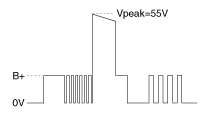
| 86 | Purge Control Solenoid Valve (PCSV) control output | Inactive Active | Pulse | High: Battery Voltage |
| Low: Max. 1.0V | ||||
| Vpeak: 42.0 ~ 60.0V | ||||
| Frequency: 20Hz | ||||
| 87 | Canister Close Valve (CCV) control output | Active Inactive | Pulse | High: Battery Voltage |
| Low: Max. 1.0V | ||||
| Vpeak: 42.0 ~ 60.0V | ||||
| 88 | Heated Oxygen Sensor (HO2S) [Bank 1/Sensor 1] Heater control output | Engine Running | Pulse | High: Battery Voltage |
| Low: -0.3 ~ 1.0V | ||||
| Frequency: 8 ~ 10Hz | ||||
| Duty: 0 ~ 100% | ||||
| 89 | Heated Oxygen Sensor (HO2S) [Bank 1/Sensor 2] Heater control output | Engine Running | Pulse | High: Battery Voltage |
| Low: -0.3 ~ 1.0V | ||||
| Frequency: 8 ~ 10Hz | ||||
| Duty: 0 ~ 100% | ||||
| 90 | Fuel Pressure Regulator Valve [High] control output | Engine Running | PWM |
|
| 91 | Fuel Pressure Regulator Valve [Low] control output | Engine Running | Pulse |
|
| Circuit Diagram |
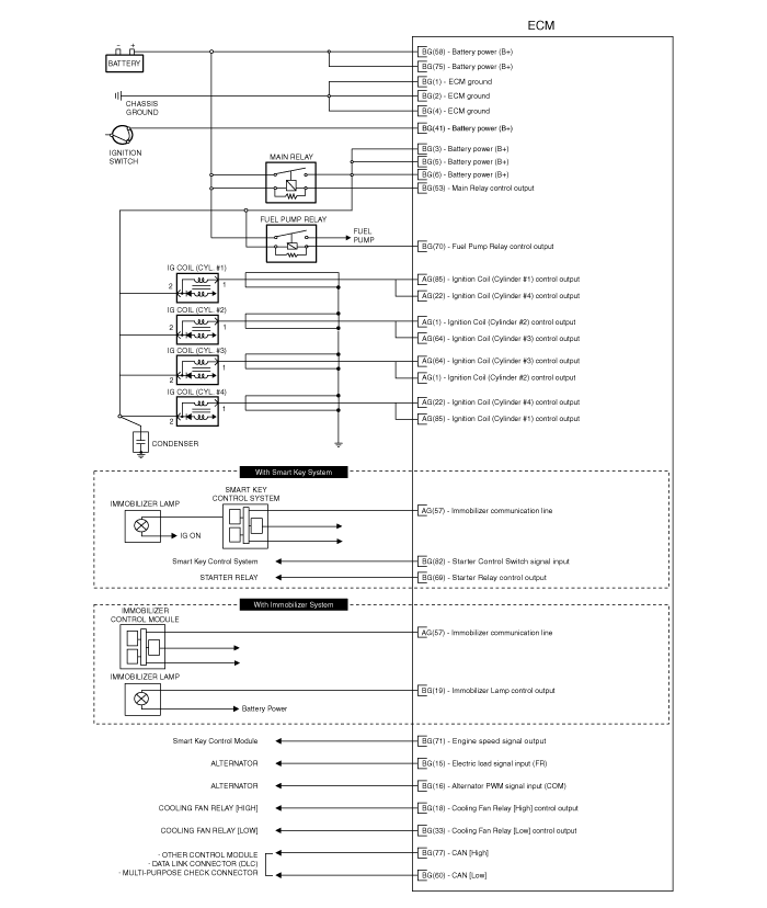
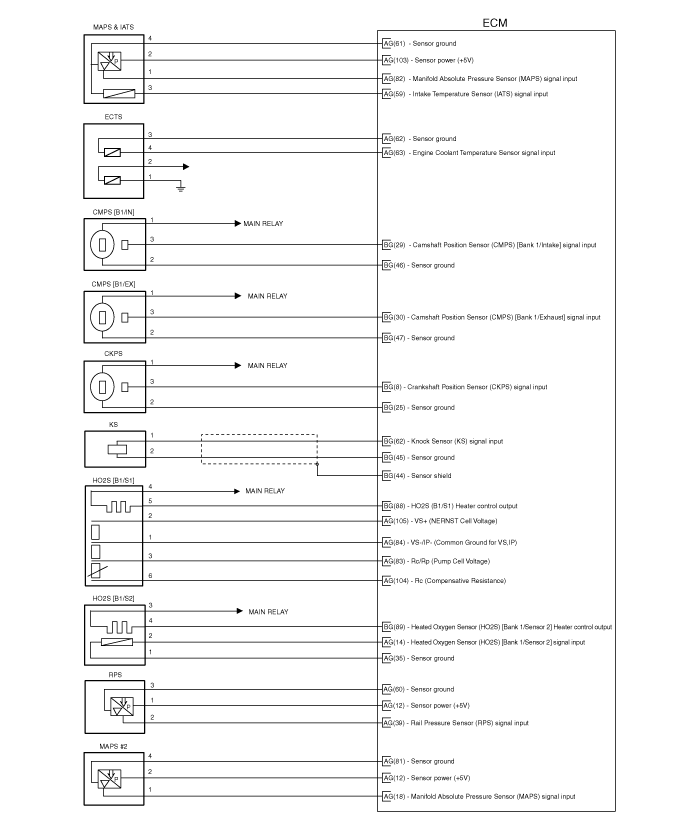
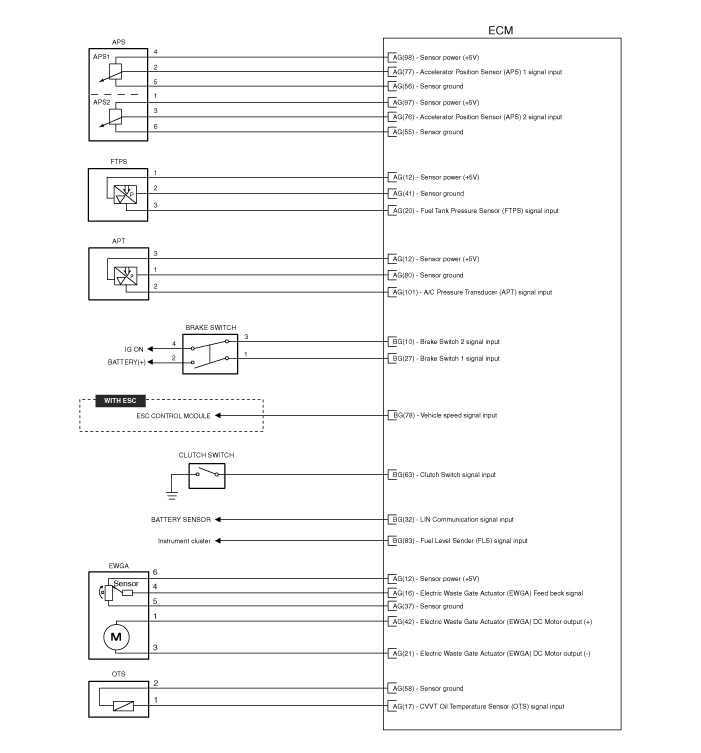
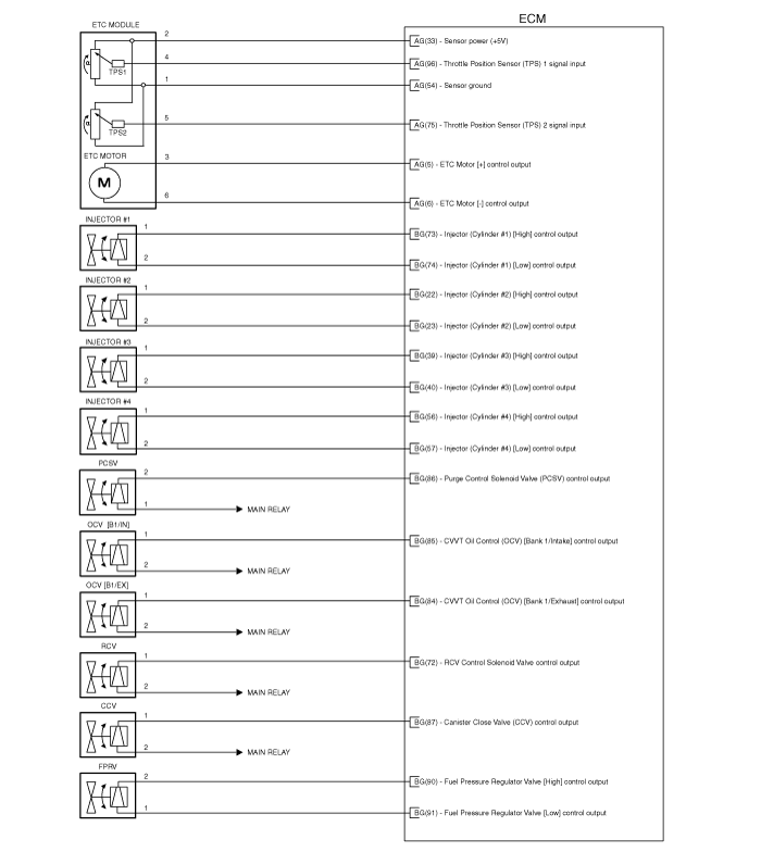
 Components and Components Location
Components Location
1. Engine Control Module (ECM)2. Manifold Absolute Pressure Sensor (MAPS) #13. Intake Air Temperature Sensor (IATS)4. Manifold Absolute Pressure Sensor (MAPS) #25. Engine Coo ...
 Engine Control Module (ECM): Repair procedures
Removal
1.
Turn ignition switch OFF and disconnect the negative (-) battery cable.
2.
Disconnect the ECM Connector (A).
3.
Remove the battery (Refer to "Intake And Exhaust System" in EM gr ...
Other Information:
Intake Actuator: Description and Operation
Description
1.
The intake actuator is located at the blower unit.
2.
It regulates the intake door by signal from control unit.
3.
Pressing the intake selection switch will shift between re ...
Front Bumper: Components and Components Location
Components
1. Front bumper cover2. Front bumper side bracket [LH]3. Front bumper side bracket [RH]
...
Categories
- Home
- Kia Sportage QL (2015-2019) Owners Manual
- Kia Sportage QL (2015-2019) Service Manual
- Kia Sportage SL 2010-2016 Owners Manual
- Kia Sportage SL 2010-2016 Service Manual
Copyright ® www.kispmanual.com 2014-2026

