 Kia Sportage: Fuel Tank: Repair procedures
Third generation SL (2010ŌĆō2016) / Kia Sportage SL Service & Repair Manual / Engine Control / Fuel System / Fuel Delivery System / Fuel Tank: Repair procedures
| Removal |
| 1. |
Release the residual pressure in fuel line (Refer to the Fuel
Delivery System - Repair Procedures - "Release Residual Pressure in
Fuel Line"). |
| 2. |
Remove the rear seat cushion (Refer to ŌĆ£SeatŌĆØ in BD group). |
| 3. |
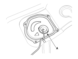
Remove the fuel pump service cover (A).
|
| 4. |
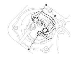
Disconnect the fuel pump connector (A) and the fuel tank pressure sensor connector (B). |
| 5. |
Disconnect the fuel feed tube quick connector (C).
|
| 6. |
Remove the rear - LH wheel & tire. |
| 7. |
Lift the vehicle and support the fuel tank with a jack. |
| 8. |
Remove the center muffler assembly (Refer to ŌĆ£Intake And Exhaust SystemŌĆØ in EM group). |
| 9. |
Remove the propeller shaft (Refer to ŌĆ£Propeller Shaft AssemblyŌĆØ in DS group) [4WD]. |
| 10. |
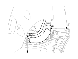
Disconnect the fuel filler hose (A) and the ventilation hose (B).
|
| 11. |
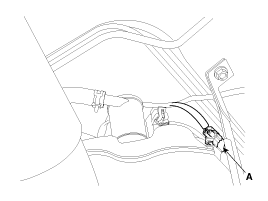
Disconnect thd canister close valve connector (A).
|
| 12. |
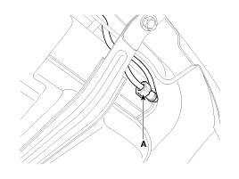
Disconnect the vapor tube quick-connector (A).
|
| 13. |
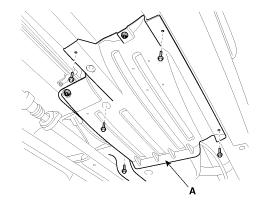
Remove the under cover (A).
|
| 14. |
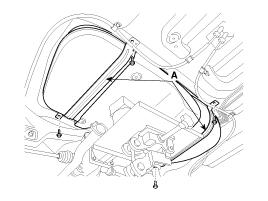
Remove the fuel tank from the vehicle after removing the fuel tank band (A).
|
| Installation |
| 1. |
Installation is reverse of removal.
|
 Repair procedures
Fuel Pressure Test (Low pressure system)
1.
Release the residual pressure in fuel line (Refer to the Fuel
Delivery System - Repair Procedures - "Release Residual Pressure in
Fuel Line").
...
 Fuel Pump: Repair procedures
Inspection
[Fuel pump]
1.
Turn the ignition switch OFF, and then remove battery (-) cable.
2.
Remove the fuel pump assembly.
3.
Check motor operation by fuel pump connector (A) connecti ...
Other Information:
Starter Relay: Repair procedures
Inspection
1.
Remove the fuse box cover.
2.
Remove the starter relay (A).
3.
Using an ohmmeter, check that there is continuity between each terminal.
TerminalContinuity30 - 87NO85 - 86Y ...
Power Window Switch: Components and Components Location
Components
Power Window Main Switch
Passenger Power Window Switch
Rear Power Window Switch
...
Categories
- Home
- Kia Sportage QL (2015-2019) Owners Manual
- Kia Sportage QL (2015-2019) Service Manual
- Kia Sportage SL 2010-2016 Owners Manual
- Kia Sportage SL 2010-2016 Service Manual
Copyright ® www.kispmanual.com 2014-2026

