 Kia Sportage: Heated Oxygen Sensor (HO2S): Repair procedures
Third generation SL (2010ŌĆō2016) / Kia Sportage SL Service & Repair Manual / Engine Control / Fuel System / Engine Control System / Heated Oxygen Sensor (HO2S): Repair procedures
| Inspection |
| 1. |
Turn the ignition switch OFF. |
| 2. |
Disconnect the HO2S connector. |
| 3. |
Measure resistance between the HO2S terminals 4 and 5 [B1/S1]. |
| 4. |
Measure resistance between the HO2S terminals 3 and 4 [B1/S2]. |
| 5. |
Check that the resistance is within the specification.
|
| Removal |
| [Bank 1 / Sensor 1] |
| 1. |
Turn the ignition switch OFF and disconnect the battery negative (-) cable. |
| 2. |
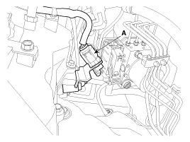
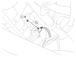
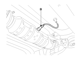
Disconnect the connector (A), and then remove the sensor (B).
|
| [Bank 1 / Sensor 2] |
| 1. |
Turn the ignition switch OFF and disconnect the battery negative (-) cable. |
| 2. |
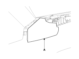
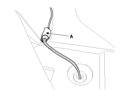
Remove the console side cover (A).
|
| 3. |
Disconnect the connector (A), and then remove the sensor (B).
|
| Installation |
|
|
| 1. |
Installation is reverse of removal.
|
 Heated Oxygen Sensor (HO2S): Schematic Diagrams
Circuit Diagram
...
 Rail Pressure Sensor (RPS): Description and Operation
Description
Rail Pressure Sensor (RPS) is installed on the delivery pipe
and measures the instantaneous fuel pressure in the delivery pipe. The
sensing element (Semiconductor element) built in ...
Other Information:
Jack label
Type A
Type B
Type C
1. Model Name
2. Maximum allowable load
3. When using the jack, set your parking brake.
4. When using the jack, stop the engine.
5. Do not get under a vehicle that is ...
Underdrive Brake Control Solenoid Valve(UD/B_VFS): Specifications
Specifications
Direct control VFS[UD/B]
? Control type : Normal high type
Control Pressure kpa (kgf/cm?, psi)500.14 ~ 9.81 (5.1 ~ 0.1, 72.54 ~ 1.42)Current value(mA)50 ~ 850 Internal resis ...
Categories
- Home
- Kia Sportage QL (2015-2019) Owners Manual
- Kia Sportage QL (2015-2019) Service Manual
- Kia Sportage SL 2010-2016 Owners Manual
- Kia Sportage SL 2010-2016 Service Manual
Copyright ® www.kispmanual.com 2014-2026


