 Kia Sportage: PDM Relay Box: Repair procedures
Third generation SL (2010ŌĆō2016) / Kia Sportage SL Service & Repair Manual / Body Electrical System / Fuses And Relays / PDM Relay Box: Repair procedures
| Removal |
PDM Relay
| 1. |
Disconnect the negative (-) battery terminal. |
| 2. |
Remove the floor console assembly.
(Refer to BD group - "Console") |
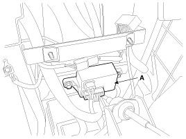
| 3. |
Remove the PDM relay box (A) after loosening the bolts (2EA) and disconnecting the connector.
|
| Installation |
| 1. |
Install the PDM relay box. |
| 2. |
Install the floor console assembly. |
| 3. |
Connect the battery (-) cable. |
| Inspection |
IG2 Relay
Check for continuity between the terminals.
| 1. |
There should be continuity between the No.1 and No.2
terminals in the B connector when power and ground are connected to the
No.3 and No.4 terminals in the A connector. |
| 2. |
There should be no continuity between the No.1 in the B and No.2 terminals in the B terminals when power is disconnected. |
IG1 Relay
Check for continuity between the terminals.
| 1. |
There should be continuity between the No.7 and No.8
terminals in the A connector when power and ground are connected to the
No.3 and No.10 terminals in the A connector. |
| 2. |
There should be no continuity between the No.7 in the A and No.8 terminals in the A terminals when power is disconnected. |
ACC Relays
Check for continuity between the terminals.
| 1. |
There should be continuity between the No.7 and No.6
terminals in the A connector when power and ground are connected to the
No.1 and No.3 terminals in the A connector. |
| 2. |
There should be no continuity between the No.7 in the A and No.6 terminals in the A terminals when power is disconnected. |
 PDM Relay Box: Description and Operation
Description
The PDM relay (A) is united with IG1, IG2 and ACC relays and installed in the lower center fascia panel. ...

Other Information:
Driving with a trailer
Towing a trailer requires a certain amount of experience. Before setting out
for the open road, you must get to know your trailer. Acquaint yourself with the
feel of handling and braking with the ...
KEY OUT indicator
When the ENGINE START/STOP button is in the ACC or ON position, if any door is
open, the system checks for the smart key. If the smart key is not in the vehicle,
the indicator will blink, and if ...
Categories
- Home
- Kia Sportage QL (2015-2019) Owners Manual
- Kia Sportage QL (2015-2019) Service Manual
- Kia Sportage SL 2010-2016 Owners Manual
- Kia Sportage SL 2010-2016 Service Manual

Copyright ® www.kispmanual.com 2014-2026