 Kia Sportage: Rear Cross Member: Repair procedures
Third generation SL (2010ŌĆō2016) / Kia Sportage SL Service & Repair Manual / Suspension System / Rear Suspension System / Rear Cross Member: Repair procedures
| Replacement |
| 1. |
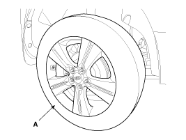
Remove the rear wheel & tire.
|
| 2. |
Remove the parking brake cable.
(Refer to "Parking Brake System" in BR group) |
| 3. |
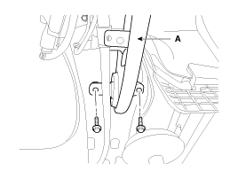
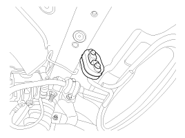
Loosen the bolt and then remove the trailing arm (A).
|
| 4. |
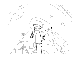
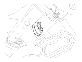
Loosen the shock absorber mounting bolts (A).
|
| 5. |
Remove the rear muffler.
|
| 6. |
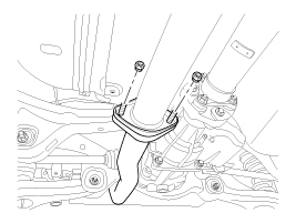
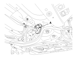
Loosen the bolt and then remove the propellar shaft (A).
|
| 7. |
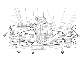
Loosen the mounting bolts and then remove the rear cross member (A) with the frame.
|
| 8. |
Remove the rear lower arm.
(Refer to lower arm) |
| 9. |
Remove the rear shock absorber.
(Refer to rear shock absorber) |
| 10. |
Remove the rear upper arm.
(Refer to rear upper arm) |
| 11. |
Remove the trailing arm.
(Refer to trailing arm) |
| 12. |
Remove the rear assist arm.
(Refer to rear assist arm) |
| 13. |
Remove the drive shaft.
(Refer to "Rear Drive Shaft" in DS group) |
| 14. |
Remove the differential carrier.
(Refer to "Differential Carrier" in DS group) |
| 15. |
Installation is the reverse of removal. |
 Trailing Arm: Repair procedures
Replacement
1.
Remove the rear wheel & tire.
Tightening torque :
88.3 ~ 107.9N.m (9.0 ~ 11.0kgf.m, 65.1 ~ 79.6lb-ft)
Be careful not to damage to the hub bol ...
 Tires/Wheels
...
Other Information:
26 Brake Control Solenoid Valve(26/B_VFS): Description and Operation
Description
26Brake control solenoid valve(26/B) is attached to the valve
body. This variable force solenoid valve directly controls the
hydraulic pressure inside the 26Brake. ...
Injector: Repair procedures
Inspection
1.
Turn the ignition switch OFF.
2.
Disconnect the injector connector.
3.
Measure resistance between the injector terminals 1 and 2.
4.
Check that the resistance is within t ...
Categories
- Home
- Kia Sportage QL (2015-2019) Owners Manual
- Kia Sportage QL (2015-2019) Service Manual
- Kia Sportage SL 2010-2016 Owners Manual
- Kia Sportage SL 2010-2016 Service Manual
Copyright ® www.kispmanual.com 2014-2025

