 Kia Sportage: Schematic Diagrams
Third generation SL (2010ŌĆō2016) / Kia Sportage SL Service & Repair Manual / Body Electrical System / Button Engine Start System / Schematic Diagrams
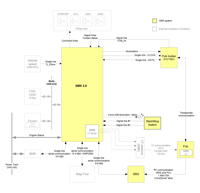
| Circuit Diagram (1) |

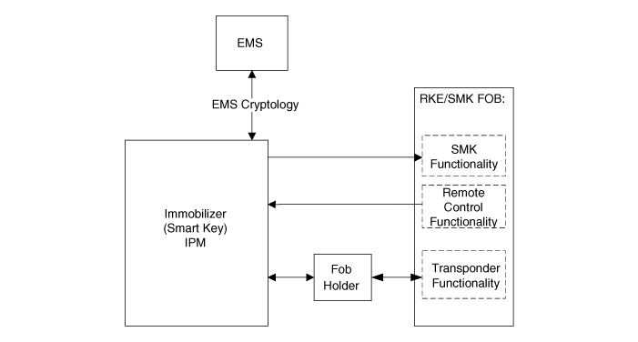
| Circuit Diagram (2) |

 Components and Components Location
Component Location
1. Start Stop Button (SSB)2. FOB key holder3. FOB key4. Tailgate switch5. Smart key unit6. RF receiver7. BCM (Body Control Module) 8. Interior ant ...
 Description and Operation
Description
System Overview
The System offers the following features:
ŌĆō
Human machine interface through a 1-stage button, for terminal switching and engine start.
ŌĆō
Control ...
Other Information:
Airbag Module Disposal: Description and Operation
Airbag Disposal
Special Tool Required
Deployment tool 0957A-34100A
Before scrapping any airbags or side airbags (including those
in a whole vehicle to be scrapped), the airbags or side airba ...
Tailgate open warning light
This warning light illuminates when the tailgate is not closed securely with
the ignition switch in any position. ...
Categories
- Home
- Kia Sportage QL (2015-2019) Owners Manual
- Kia Sportage QL (2015-2019) Service Manual
- Kia Sportage SL 2010-2016 Owners Manual
- Kia Sportage SL 2010-2016 Service Manual
Copyright ® www.kispmanual.com 2014-2025
