 Kia Sportage: Repair procedures
Third generation SL (2010ŌĆō2016) / Kia Sportage SL Service & Repair Manual / Body Electrical System / Ignition Switch Assembly / Repair procedures
| Inspection |
| 1. |
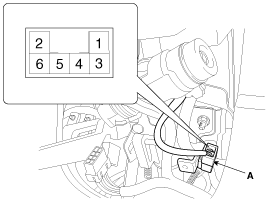
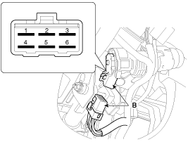
Disconnect the ignition switch connector (B) and key warning switch connector (A) from under the steering column.
|
| 2. |
Check for continuity between the terminals. |
| 3. |
If continuity is not specified, replace the switch. |

| Removal |
| 1. |
Disconnect the negative (-) battery terminal. |
| 2. |
Remove the steering column upper and lower shrouds.
(Refer to the ST group - "Steering column") |
| 3. |
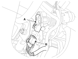
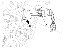
Remove the ignition switch (A) after disconnecting the 6P connector (B).
|
| 4. |
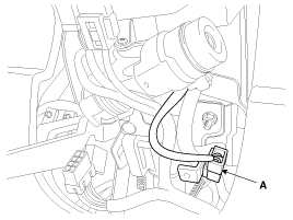
Remove the key warning and immobilizer connector (A).
|
| 5. |
Remove the key illumination cover. |
| 6. |
If it is necessary to remove the key lock cylinder (A), remove the key lock cylinder after pushing lock pin (B) with key ACC.
|
| Installation |
| 1. |
Install the key lock cylinder. |
| 2. |
Install the illumination cover. |
| 3. |
Install the key warning and immobilizer connector. |
| 4. |
Install the ignition switch. |
| 5. |
Install the steering column shrouds and crash pad lower panel. |
Other Information:
Purge Control Solenoid Valve (PCSV): Repair procedures
Inspection
1.
Turn the ignition switch OFF.
2.
Disconnect the PCSV connector.
3.
Measure resistance between the PCSV terminals 1 and 2.
4.
Check that the resistance is within the speci ...
Input Speed Sensor: Specifications
Specifications
? Type: Hall effect sensor
Operation condition (┬░C)┬░F((-)40~150)) -40~302Air gap (mm)in.(0.95~1.65) 0.0374~0.0649Output voltage(V)High1.18 ~ 1.68Low0.59 ~ 0.84
...
Categories
- Home
- Kia Sportage QL (2015-2019) Owners Manual
- Kia Sportage QL (2015-2019) Service Manual
- Kia Sportage SL 2010-2016 Owners Manual
- Kia Sportage SL 2010-2016 Service Manual
Copyright ® www.kispmanual.com 2014-2026

