Inspect and adjust the valve clearance when the engine is
cold (Engine coolant temperature : 20ô¯C (68ô¯F)) and cylinder head is
installed on the cylinder block.
In case of removing the high pressure fuel pump, high
pressure fuel pipe, delivery pipe, and injector, there may be injury
caused by leakage of the high pressure fuel. So donãt do any repair
work right after engine stops.
1.
Remove the cylinder head cover. (Refer to Timing system in this group)
2.
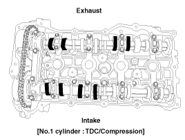
Set No.1 cylinder to TDC/compression.
(1)
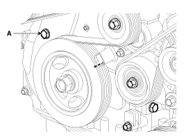
Turn the crankshaft pulley and align its groove with the timing mark "T" of the lower timing chain cover.
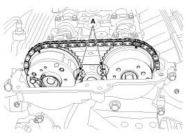
(2)
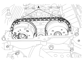
Check that the TDC marks (A) of the CVVT sprockets are in
straight line on the cylinder head surface as shown in the illustration.
If not, turn the crankshaft one revolution (360ô¯)
3.
Inspect the valve clearance.
(1)
Check only the valve indicated as shown. Measure the valve clearance.
ãÂ
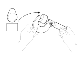
Using a thickness gauge, measure the clearance between the tappet and the base circle of camshaft.
ãÂ
Record the out-of-specification valve clearance measurements.
They will be used later to determine the required replacement adjusting
tappet.
Valve clearance [Engine coolant temperature : 20ô¯C(68ô¯F)]
[Specification]
Intake : 0.17 ~ 0.23mm (0.0067 ~ 0.0090in.)
Exhaust : 0.32 ~ 0.38mm (0.0126 ~ 0.0150 in.)
(2)
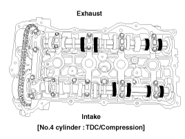
Turn the crankshaft pulley one revolution (360ô¯) and align the groove with timing mark "T" of the lower timing chain cover.
(3)
Check only valves indicated as shown. Measure the valve clearance.
4.
Adjust the intake and exhaust valve clearance.
(1)
Set the No.1 cylinder to the TDC/compression.
(2)
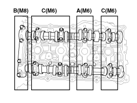
Mark the timing chains (A) on the timing marks of the CVVT sprockets.
(3)
Remove the front camshaft bearing cap.
(4)
Turn the crankshaft pulley 15ô¯ clockwise.
(5)
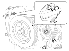
Remove the service hole bolt(A) of the timing chain cover.
The bolt must not be reused once it has been assembled.
(6)
Remove the intake and exhaust camshaft bearing caps.
(7)
Release the ratchet of the timing chain tensioner by pulling the link down using a thin rod.
(8)
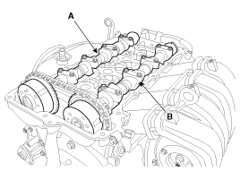
After loosening the timing chain, remove the exhaust CVVT
& camshaft assembly (A) and then the intake CVVT & camshaft
assembly (B).
When disconnect the timing chain from the CVVT sprocket, hold the timing chain.
(9)
Tie down timing chain so that it doesn''t move.
Be careful not to drop anything inside timing chain cover.
(10)
Measure the thickness of the removed tappet using a micrometer.
(11)
Calculate the thickness of a new tappet so that the valve clearance comes within the specified value.
Valve clearance [Engine coolant temperature : 20ô¯C(68ô¯F)]
T : Thickness of removed tappet
A : Measured valve clearance
N : Thickness of new tappet
Intake : N = T + [A - 0.20mm (0.0079in.)]
Exhaust : N = T + [A - 0.30mm (0.0118in.)]
(12)
Select a new tappet with a thickness as close as possible to the calculated value.
Shims are available in 47 size increments of 0.015mm (0.0006in.) from 3.00mm (0.118in.) to 3.690mm (0.1452in.)
(13)
Place a new tappet on the cylinder head.
(14)
Hold the timing chain, and place the intake CVVT & camshaft assembly.
(15)
Place the exhaust CVVT & camshaft assembly after releasing the ratchet of the timing chain tensioner.
The timing marks of each CVVT sprocket should be matched with
timing marks (painted link) of timing chain when installing the timing
chain.
(16)
Install the camshaft bearing caps in their proper locations.
Turn the crankshaft two turns in the operating direction
(clockwise), and then check that the TDC marks (A) of the CVVT sprockets
are in straight line on the cylinder head surface.
(19)
Recheck the valve clearance.
Valve clearance [Engine coolant temperature : 20ô¯C(68ô¯F)]
[Specification]
Intake : 0.17 ~ 0.23mm (0.0067 ~ 0.0090in.)
Exhaust : 0.32 ~ 0.38mm (0.0126 ~ 0.0150 in.)
(20)
Install the cylinder head cover. (Refer to Timing system in this group)
Removal
Timing chain cover removal is not required for this procedure.
ãÂ
Use fender covers to avoid damaging painted surfaces.
ãÂ
To avoid damagin ...
Other Information:
Resetting the sunroof
Whenever the vehicle battery is disconnected or discharged, you must reset your
sunroof system as follows:
1.Turn the ignition switch to the ON position.
2.Open the roller blind.
3.Close the sunr ...
Front Cross Member: Repair procedures
Replacement
1.
Remove the front wheel & tire.
Tightening torque :
88.3 ~ 107.9N.m (9.0 ~ 11.0kgf.m, 65.1 ~ 79.6lb-ft)
Be careful not to damage to the hub bo ...
 Kia Sportage: Valve Clearance Adjustment


 Camshaft: Repair procedures