 Kia Sportage: Starter Relay: Repair procedures
Third generation SL (2010ŌĆō2016) / Kia Sportage SL Service & Repair Manual / Engine Electrical System / Starting System / Starter Relay: Repair procedures
| Inspection |
| 1. |
Remove the fuse box cover. |
| 2. |
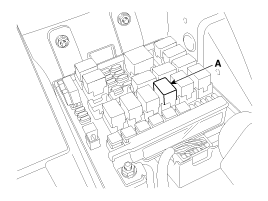
Remove the starter relay (A).
|
| 3. |
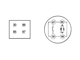
Using an ohmmeter, check that there is continuity between each terminal.
|
| 4. |
Apply 12V to terminal 85 and ground to terminal 86.
Check for continuity between terminals 30 and 87.
|
| 5. |
If there is no continuity, replace the starter relay. |
| 6. |
Install the starter relay. |
| 7. |
Install the fuse box cover. |
 Starter: Repair procedures
Removal and Installation
1.
Remove the engine cover.
2.
Disconnect the battery negative terminal (A).
Tightening torque :
4.0 ~ 6.0N.m (0.4 ~ 0.6kgf.m, 3.0 ~ 4.4lb-ft)
3.
Remove the ...
Other Information:
Explanation of scheduled maintenance items
Engine oil and filter
The engine oil and filter should be changed at the intervals specified in the
maintenance schedule. If the vehicle is being driven in severe conditions, more
frequent oil an ...
Blower Unit: Components and Components Location
Component Location
Components
1. Intake case (LH)2. Intake case (RH)3. Blower motor4. Intake door5. Intake actuator6. Mofet [Auto type]7. Resistor [Manual type]8. Climate control air filter cove ...
Categories
- Home
- Kia Sportage QL (2015-2019) Owners Manual
- Kia Sportage QL (2015-2019) Service Manual
- Kia Sportage SL 2010-2016 Owners Manual
- Kia Sportage SL 2010-2016 Service Manual
Copyright ® www.kispmanual.com 2014-2026


