 Kia Sportage: Balance Shaft & Oil Pump: Repair procedures
Third generation SL (2010ŌĆō2016) / Kia Sportage SL Service & Repair Manual / Engine Mechanical System / Lubrication System / Balance Shaft & Oil Pump: Repair procedures
| Removal |
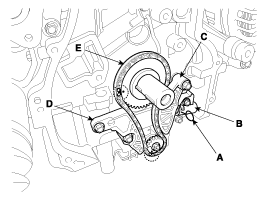
BSM (Balance Shaft Module) Chain System
| 1. |
Remove the timing chain.
(Refer to Timing System in this group) |
| 2. |
Install a stopper pin (A) after compressing the balance shaft chain tensioner. |
| 3. |
Remove the balance shaft chain tensioner (B). |
| 4. |
Remove the balance shaft chain tensioner arm (C). |
| 5. |
Remove the balance shaft chain guide (D). |
| 6. |
Remove the balance shaft chain (E).
|
| 7. |
Remove the BSM (Balance Shaft Module) after removing the BSM mounting bolts.
|

BSM (Balance Shaft Module)
| 1. |
Remove the under cover. |
| 2. |
Remove the RH front wheel. |
| 3. |
Drain the engine oil. |
| 4. |
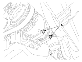
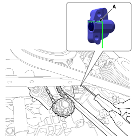
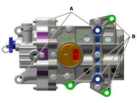
Remove the A/C compressor lower mounting bolts (A).
|
| 5. |
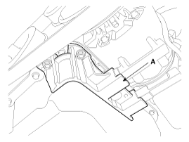
Remove the A/C compressor bracket (A).
|
| 6. |
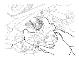
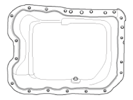
Remove the oil pan (A) after removing the bolts.
Insert the blade of SST (09215-3C000) between the ladder frame and oil pan. Cut off applied sealer and remove the lower oil pan.
|
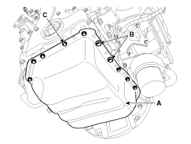
 arrow.
 arrow around more than 2/3 edge of the oil pan, remove it from the ladder frame.
| 7. |
Set No.1 cylinder to TDC/compression.
|
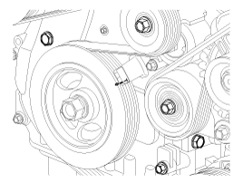
| 8. |
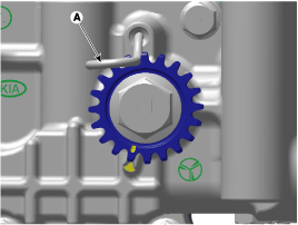
Put a mark on the timing chain (A) corresponding to the timing mark (B) of the sprocket.
|
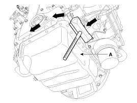
| 9. |
Insert a stopper pin (A) into the hole on the tensioner after compressing the balance shaft chain tensioner piston.
|
| 10. |
Remove the BSM mounting bolts.
|
| 11. |
Remove the BSM (Balance Shaft Module) (A) while taking off the chain from the sprocket.
|
| Installation |
BSM(Balance Shaft Module) Chain System
| 1. |
The key of crankshaft should be aligned with the mating face
of main bearing cap. As a result of this, the piston of No.1 cylinder is
placed at the top dead center on compression stroke. |
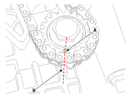
| 2. |
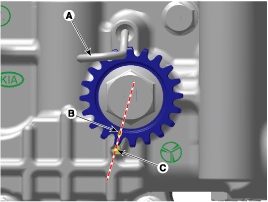
Insert a stopper pin (A) on the BSM to hold the sprocket at
the reference position with the timing mark (B) aligned with the timing
notch (C).
|

| 3. |
Install the BSM (Balance Shaft Module).
|
| 4. |
Install the balance shaft chain (E).
|
| 5. |
Install the balance shaft chain guide (D).
|
| 6. |
Install the balance shaft chain tensioner arm (C).
|
| 7. |
Install the balance shaft chain tensioner (B) then remove the stopper pin (A).
|
| 8. |
Remove the stopper pin (A) of balance shaft module.
|
| 9. |
After rotating crankshaft 2 revolutions in regular direction
(clockwise viewed from front), confirm that the timing mark and notch
are aligned at the reference position. |
| 10. |
Install the other parts in the reverse order of removal. |
BSM (Balance Shaft Module)
| 1. |
Insert a stopper pin (A) on the BSM to hold the sprocket at
the reference position with the timing mark (B) aligned with the timing
notch (C).
|
| 2. |
Install the BSM (Balance Shaft Module) (A).
|
| 3. |
Install the BSM mounting bolts.
|
| 4. |
Remove the stopper pin (A) from the BSM.
|
| 5. |
Remove the stopper pin (A) from the tensioner.
|
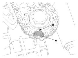
| 6. |
Confirm the BSM timing mark.
|
| 7. |
Install the oil pan.
|
| 8. |
Install the A/C compressor bracket (A).
|
| 9. |
Remove the A/C compressor lower mounting bolts (A).
|
| 10. |
Refill with engine oil. |
| 11. |
Install the RH front wheel. |
| 12. |
Install the under cover. |
 Balance Shaft & Oil Pump: Components and Components Location
Components
1. Balance shaft & oil pump assembly2. Balance shaft chain tensioner3. Balance shaft chain4. Balance shaft chain sprocket5. Balance shaft chain guide6. Balance shaft chain tensione ...
 Oil Cooler: Repair procedures
Removal
1.
Loosen the drain plug, and drain the coolant. Remove the radiator cap to speed draining.
2.
Disconnect the oil cooler coolant hoses (A).
3.
Remove the oil filter (A).
4.
Loo ...
Other Information:
Evaporator Temperature Sensor: Repair procedures
Inspection
1.
Ignition "OFF".
2.
Disconnect evaporator temperature sensor.
3.
Using the multi-tester, Measure resistance between terminal "1" and "2" of evaporator temperature sensor.
Spe ...
Special Service Tools
Special Service Tools
Tool (Number and name)IllustrationUseAlternator pulley remover wrench(09373-27000)Removal and installation of alternator pulley
...
Categories
- Home
- Kia Sportage QL (2015-2019) Owners Manual
- Kia Sportage QL (2015-2019) Service Manual
- Kia Sportage SL 2010-2016 Owners Manual
- Kia Sportage SL 2010-2016 Service Manual

Copyright ® www.kispmanual.com 2014-2026