 Kia Sportage: Description and Operation
Third generation SL (2010ŌĆō2016) / Kia Sportage SL Service & Repair Manual / Body Electrical System / Immobilizer System / Description and Operation
| Description |
The immobilizer system will disable the vehicle unless the
proper ignition key is used, in addition to the currently available
anti-theft systems such as car alarms, the immobilizer system aims to
drastically reduce the rate of auto theft.
| 1. |
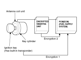
Encrypted SMARTRA type immobilizer
|
| Components Operations |
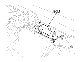
PCM (Power Train Control Module)
| 1. |
The PCM(ECM) (A) carries out a check of the ignition key
using a special encryption algorithm, which is programmed into the
transponder as well as the PCM(ECM) simultaneously. Only if the results
are equal, the engine can be started. The data of all transponders,
which are valid for the vehicle, are stored in the PCM(ECM).
ERN (Encrypted Random Number) value between EMS and encrypted
smartra unit is checked and the validity of coded key is decided by
EMS.
|
ENCRYPTED SMARTRA unit (A)
The SMARTRA carries out communication with the built-in
transponder in the ignition key. This wireless communication runs on RF
(Radio frequency of 125 kHz). The SMARTRA is mounted behind of the crash
pad close to center cross bar.
The RF signal from the transponder, received by the antenna
coil, is converted into messages for serial communication by the SMARTRA
device. And, the received messages from the PCM(ECM) are converted into
an RF signal, which is transmitted to the transponder by the antenna.
The SMARTRA does not carry out the validity check of the
transponder or the calculation of encryption algorithm. This device is
only an advanced interface, which converts the RF data flow of the
transponder into serial communication to the PCM(ECM) and vice versa.
[USA]
[Canada]
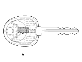
TRANSPONDER (Built-in keys)
The transponder (A) has an advanced encryption algorithm.
During the key teaching procedure, the transponder will be programmed
with vehicle specific data. The vehicle specific data are written into
the transponder memory. The write procedure is once only; therefore, the
contents of the transponder can never be modified or changed.
| [Key Type] |
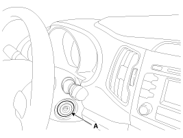
Antenna coil
The antenna coil (A) has the following functions.
| ŌĆō |
The antenna coil supplies energy to the transponder. |
| ŌĆō |
The antenna coil receives signal from the transponder. |
| ŌĆō |
The antenna coil sends transponder signal to the SMARTRA.
It is located directly in front of the steering handle lock. |
 Schematic Diagrams
Circuit Diagram
...
 Repair procedures
Replacement
Problems And Replacement Parts:
ProblemPart setScan tool required?All keys have been lostBlank key (4)YESAntenna coil unit does not workAntenna coil unitNOECM does not workPCM(ECM)YE ...
Other Information:
To defog inside windshield
1.Set the fan speed to the desired position.
2.Select desired temperature.
3.Press the defroster button ().
4.The outside (fresh) air position will be selected automatically and the air
conditi ...
Compressor: Components and Components Location
Components
1. Bolt2. Disc & Hub Assembly 3. Retainer Ring (Pulley)4. Pulley5. Retainer Ring (Field coil)6. Field Coil7. Compressor Assembly
...
Categories
- Home
- Kia Sportage QL (2015-2019) Owners Manual
- Kia Sportage QL (2015-2019) Service Manual
- Kia Sportage SL 2010-2016 Owners Manual
- Kia Sportage SL 2010-2016 Service Manual

Copyright ® www.kispmanual.com 2014-2026