 Kia Sportage: Intake Actuator: Repair procedures
Third generation SL (2010ŌĆō2016) / Kia Sportage SL Service & Repair Manual / Heating,Ventilation, Air Conditioning / Blower / Intake Actuator: Repair procedures
| Inspection |
| 1. |
Ignition "OFF" |
| 2. |
Disconnect the intake actuator connector. |
| 3. |
Verify that the actuator operates to the recirculation position when connecting 12V to the terminal 3 and grounding terminal 4. |
| 4. |
Verify that the intake actuator operates to the fresh position when connecting in the reverse.
|
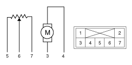
| 5. |
Check the voltage between terminals 6 and 7.
|
| 6. |
If the intake actuator is not operated well, substitute with a known-good intake actuator and check for proper operation. |
| 7. |
If the problem is corrected, replace the intake actuator. |
| Replacement |
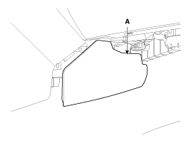
| 1. |
Disconnect the negative (-) battery terminal. |
| 2. |
Remove the right extension cover (A).
|
| 3. |
Remove the crash pad.
(Refer to BD group - "Crash Pad") |
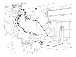
| 4. |
Remove the right shower duct (A).
|
| 5. |
Disconnect the Intake actuator connector (A). |
| 6. |
Loosen the mounting screw and then remove the intake actuator (B).
|
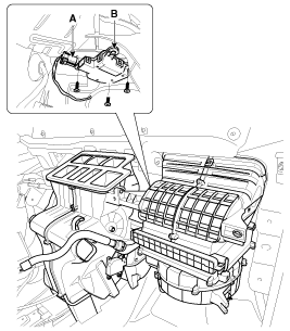
| 7. |
Installation is the reverse order of removal. |
 Intake Actuator: Description and Operation
Description
1.
The intake actuator is located at the blower unit.
2.
It regulates the intake door by signal from control unit.
3.
Pressing the intake selection switch will shift between re ...
 Controller
...
Other Information:
Seat Belt Pretensioner (BPT): Components and Components Location
Components
...
High Mounted stop lamp: Repair procedures
Removal
High Mounted Stop Lamp
1.
Disconnect the negative (-) battery terminal.
2.
Remove the tailgate trim.
(Refer to the BD group - "Tailgate")
3.
Remove the spoiler.
(Refer to the ...
Categories
- Home
- Kia Sportage QL (2015-2019) Owners Manual
- Kia Sportage QL (2015-2019) Service Manual
- Kia Sportage SL 2010-2016 Owners Manual
- Kia Sportage SL 2010-2016 Service Manual

Copyright ® www.kispmanual.com 2014-2026