 Kia Sportage: Manifold Absolute Pressure Sensor (MAPS): Repair procedures
Third generation SL (2010ŌĆō2016) / Kia Sportage SL Service & Repair Manual / Engine Control / Fuel System / Engine Control System / Manifold Absolute Pressure Sensor (MAPS): Repair procedures
| Inspection |
| 1. |
Connect the GDS on the Data Link Connector (DLC). |
| 2. |
Measure the output voltage of the MAPS at idle and IG ON.
|
| Removal |
| 1. |
Turn the ignition switch OFF and disconnect the battery negative (-) cable. |
| 2. |
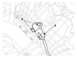
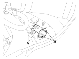
Disconnect the manifold absolute pressure sensor connector (A). |
| 3. |
Remove the installation bolts (B), and then remove the sensor from the surge tank.
[MAPS #1]
[MAPS #2]
|
| Installation |
|
|
| 1. |
Installation is reverse of removal.
|
 Manifold Absolute Pressure Sensor (MAPS): Schematic Diagrams
Circuit Diagram
...
 Intake Air Temperature Sensor (IATS): Description and Operation
Description
Intake Air Temperature Sensor (IATS) is included inside
Manifold Absolute Pressure Sensor and detects the intake air
temperature.
To calculate precise air quantity, correction of t ...
Other Information:
Compression Test
Compression Pressure Inspection
If the there is lack of power, excessive oil consumption or poor fuel economy, measure the compression pressure.
1.
Warm up and stop ...
Front Disc Brake: Repair procedures
Removal
1.
Remove the front wheel & tire.
Tightening torque:
88.3 ~107.9 N.m (9.0 ~11.0 kgf.m, 65.1 ~79.6 lb-ft)
2.
Loosen the hose eyebolt (B) and caliper mounting bolts (C), then ...
Categories
- Home
- Kia Sportage QL (2015-2019) Owners Manual
- Kia Sportage QL (2015-2019) Service Manual
- Kia Sportage SL 2010-2016 Owners Manual
- Kia Sportage SL 2010-2016 Service Manual
Copyright ® www.kispmanual.com 2014-2026


