 Kia Sportage: Seat Belt Pretensioner (BPT): Repair procedures
Third generation SL (2010ŌĆō2016) / Kia Sportage SL Service & Repair Manual / Restraint / Seat Belt Pretensioner / Seat Belt Pretensioner (BPT): Repair procedures
| Removal |
| 1. |
Disconnect the battery negative cable, and wait for at least thirty seconds before beginning work. |
| 2. |
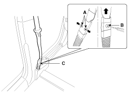
To remove the seat belt anchor pretensioner (C), keep on
pushing the lock pins (A) as arrow direction. And then remove the seat
belt after pushing the lock pin (B).
|
| 3. |
Remove the following parts. (Refer to the Body group- Interior trim)
|
| 4. |
Remove the upper anchor bolt. |
| 5. |
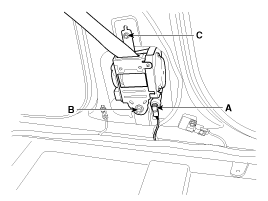
Disconnect the seat belt pretensioner connector (A).
|
| 6. |
Loosen the seat belt pretensioner mounting bolt (B,C) and remove the seat belt pretensioner. |
| Installation |
| 1. |
Remove the ignition key from the vehicle. |
| 2. |
Disconnect the battery negative cable and wait for at least thirty seconds. |
| 3. |
Install the seat belt pretensioner (BPT) with a bolt.
|
| 4. |
Connect the seat belt pretensioner (BPT) connector. |
| 5. |
Install the upper anchor bolts.
|
| 6. |
Install the following parts. . (Refer to the Body group- Interior trim)
|
| 7. |
Insert the seat belt to the anchor pretensioner. |
| 8. |
Reconnect the battery negative cable. |
| 9. |
After installing the seat belt pretensioner (BPT), confirm proper system operation:
|
 Anchor Pretensioner: Description and Operation
Description
Anchor pretensioner operates as well as belt Pretensioner at
the same time If it gets into its deploy condition after a collision. It
is located at near anchor on front seat and it ...
Other Information:
Troubleshooting
Engine Overheat Troubleshooting
Inspection RemedyVisual inspectionInspect for shortage of coolant in reservoir tank .Reinspect after replenishing coolant.Inspect for coolant pollution after remo ...
Input Speed Sensor: Troubleshooting
Signal Waveform
Fig 1) Input/Output speed sensor at low speed
Fig 2) Input/Output speed sensor at high speed ...
Categories
- Home
- Kia Sportage QL (2015-2019) Owners Manual
- Kia Sportage QL (2015-2019) Service Manual
- Kia Sportage SL 2010-2016 Owners Manual
- Kia Sportage SL 2010-2016 Service Manual
Copyright ® www.kispmanual.com 2014-2026


