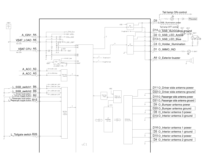
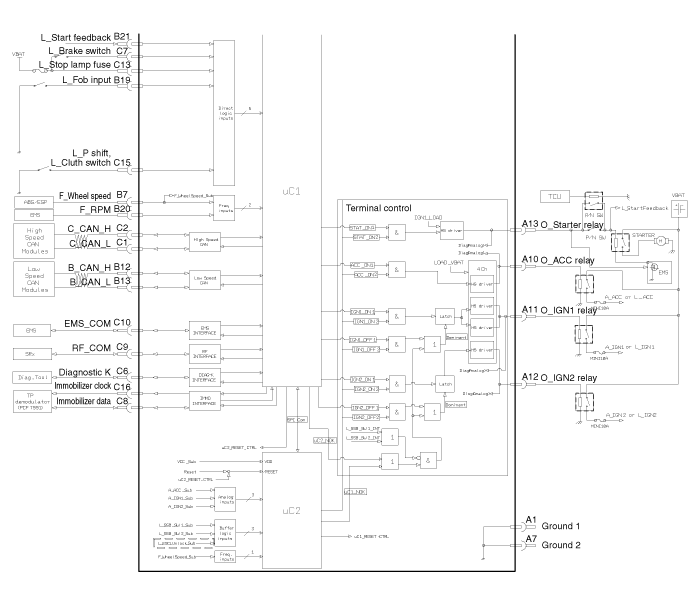
 Kia Sportage: Smart key unit: Schematic Diagrams
Third generation SL (2010â2016) / Kia Sportage SL Service & Repair Manual / Body Electrical System / Smart key System / Smart key unit: Schematic Diagrams
| Circuit Diagram |


 Smart key unit: Components and Components Location
Components
Connector Pin Information
NoConnector A (14 Pin)NoConnector B (26 Pin)1Ground 11 -15L_Passenger lock button, L_Passenger toggle button2A_ACC2L_Driver lock button,L_Driver toggle ...
 Smart key unit: Repair procedures
Removal
Smart Key Unit
1.
Disconnect the negative (-) battery terminal.
2.
Remove the glove box.
(Refer to the BD group - "Crash pad")
3.
After disconnecting the smart key unit connector ...
Other Information:
BluetoothÂź Wireless Technology
BluetoothÂź Wireless Technology
The BluetoothÂź word mark and logos are registered trademarks owned by Bluetooth
SIG, lnc. and any use of such marks by Kia is under license.
A BluetoothÂź enabled ...
Description and Operation
Function
Bluetooth Audio System
Bluetooth
You can use a Bluetooth device in your car to make a
hands-free phone call or to stream music onto your in-car speakers (via
this Head Unit). This ...
Categories
- Home
- Kia Sportage QL (2015-2019) Owners Manual
- Kia Sportage QL (2015-2019) Service Manual
- Kia Sportage SL 2010-2016 Owners Manual
- Kia Sportage SL 2010-2016 Service Manual
Copyright © www.kispmanual.com 2014-2026
