 Kia Sportage: Engine And Transaxle Assembly: Repair procedures
Third generation SL (2010ŌĆō2016) / Kia Sportage SL Service & Repair Manual / Engine Mechanical System / Engine And Transaxle Assembly / Engine And Transaxle Assembly: Repair procedures
| Removal |
|

|

| 1. |
Remove the engine cover. |
| 2. |
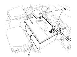
Disconnect the battery terminals (A).
|
| 3. |
Remove the battery (B) after removing the mounting bracket (C).
|
| 4. |
Remove the air cleaner assembly.
|
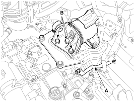
| 5. |
Remove the ECM (A) after disconnecting the connectors (B). (Refer to FL group)
|
| 6. |
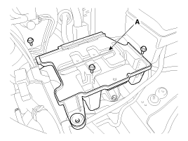
Remove the battery tray (A).
|
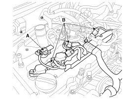
| 7. |
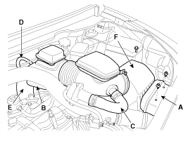
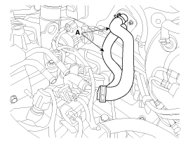
Disconnect the recirculation valve connector (A) and the
vacuum hose (B), and then remove the intercooner inlet pipe & hose
assembly (C).
|
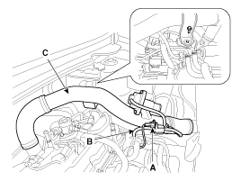
| 8. |
Disconnect the boost pressure sensor connector (A) and then remove the intercooler outlet pipe & hose assembly (B).
|
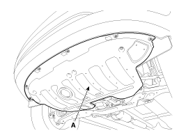
| 9. |
Remove the under cover (A).
|
| 10. |
Loosen the drain plug, and drain the engine coolant. Remove
the radiator cap to drain with speed. (Refer to Cooling system in this
group) |
| 11. |
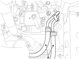
Disconnect the radiator upper hose (A) and lower hose (B).
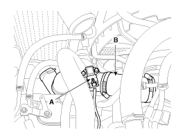
|
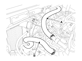
| 12. |
Recover the refrigerant and then remove the high pressure
pipe (A) and low pressure pipe (B). (Refer to Air conditioning system in
HA Group.)
|
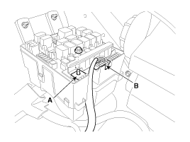
| 13. |
Disconnect the (+) cable (A) and connector (B) from the fuse/relay box.
|
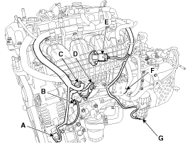
| 14. |
Disconnect the wiring connectors and harness clamps, and
remove the wiring protectors from the cylinder head, intake manifold and
exhaust manifold.
|
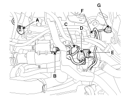
| 15. |
Remove the transaxle wire harness connectors (A) and control cable (B) from the transaxle. (Refer to AT group).
|
| 16. |
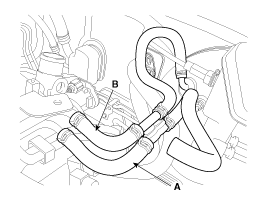
Disconnect the ATF cooler hoses (A).
|
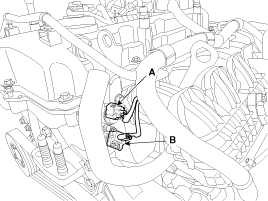
| 17. |
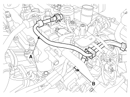
Disconnect the intensifier hose (A) and the vacuum hose (B).
|
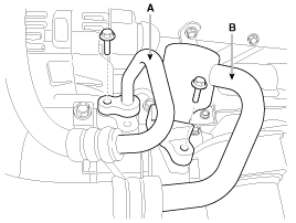
| 18. |
Disconnect the fuel hose (A) and PCSV (Purge control solenoid valve) hose (B).
|
| 19. |
Disconnect the heater hoses (A).
|
| 20. |
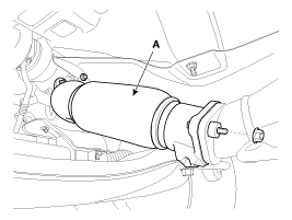
Remove the front muffler (A).
|
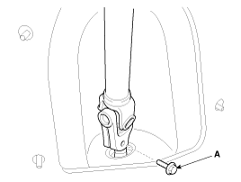
| 21. |
Remove the steering u-joint mounting bolt (A). (Refer to ST group)
|
| 22. |
Remove the front wheels. |
| 23. |
Remove the lower arms (A). (Refer to SS group)
|
| 24. |
Remove the stabilizer bar links (A). (Refer to SS group)
|
| 25. |
Remove the tie rod ends (A). (Refer to ST group)
|
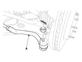
| 26. |
Disconnect the drive shafts (A) from the axle hubs. (Refer to DS group)
|
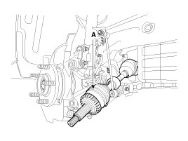
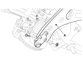
| 27. |
Remove the roll rod bracket (A).
|
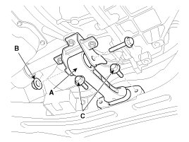
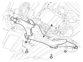
| 28. |
Support the sub frame (A) with a floor jack, and then remove the sub frame mounting bolts and nuts.
|
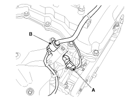
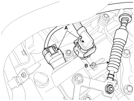
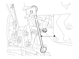
| 29. |
Disconnect the ground line (A), and then remove the engine mounting support bracket (B).
|
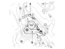
| 30. |
Disconnect the ground line (A), and then remove the transaxle mounting support bracket (B).
|
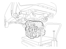
| 31. |
Remove the engine and transaxle assembly by lifting vehicle.
|
| Installation |
Installation is in the reverse order of removal.
Perform the following :
| ŌĆó |
Adjust a shift cable. |
| ŌĆó |
Refill engine with engine oil. |
| ŌĆó |
Refill a transaxle with fluid. |
| ŌĆó |
Refill a radiator and a reservoir tank with engine coolant. |
| ŌĆó |
Clean battery posts and cable terminals and assemble. |
| ŌĆó |
Inspect for fuel leakage. |
| ŌĆō |
After assemble the fuel line, turn on the ignition switch (do
not operate the starter) so that the fuel pump runs for approximately
two seconds and fuel line pressurizes. |
| ŌĆō |
Repeat this operation two or three times, then check for fuel leakage at any point in the fuel line. |
| ŌĆó |
Bleed air from the cooling system. |
| ŌĆō |
Start engine and let it run until it warms up. (until the radiator fan operates 3 or 4 times.) |
| ŌĆō |
Turn Off the engine. Check the level in the radiator, add
coolant if needed. This will allow trapped air to be removed from the
cooling system. |
| ŌĆō |
Put radiator cap on tightly, then run the engine again and check for leaks. |
 Engine Mounting: Components and Components Location
Components
1. Transaxle mounting bracket 2. Roll rod bracket3. Sub frame 4. Engine mounting bracket5. Engine mounting support bracket
...
 Timing System
...
Other Information:
Using a child restraint system
Rearward-facing child restraint system
Forward-facing child restraint system
For small children and babies, the use of a child seat or infant seat is required.
The child seat or infant seat sho ...
General Safety Information and Caution
Instructions
When Handling Refrigerant
1.
R-134a liquid refrigerant is highly volatile. A drop on the
skin of your hand could result in localized frostbite. When handling the
refrigerant, be ...
Categories
- Home
- Kia Sportage QL (2015-2019) Owners Manual
- Kia Sportage QL (2015-2019) Service Manual
- Kia Sportage SL 2010-2016 Owners Manual
- Kia Sportage SL 2010-2016 Service Manual

Copyright ® www.kispmanual.com 2014-2026