Timing chain cover removal is not required for this procedure.
ŌĆó
Use fender covers to avoid damaging painted surfaces.
ŌĆó
To avoid damaging the cylinder head, wait until the engine
coolant temperature drops below normal temperature before removing it.
ŌĆó
To avoid damage, unplug the wiring connectors carefully while holding the connector portion.
ŌĆó
Mark all wiring and hoses to avoid misconnection.
ŌĆó
Turn the crankshaft pulley so that the No. 1 piston is at top dead center.
In case of removing the high pressure fuel pump, high
pressure fuel pipe, delivery pipe, and injector, there may be injury
caused by leakage of the high pressure fuel. So donŌĆÖt do any repair
work right after engine stops.
1.
Remove the cylinder head cover. (Refer to Timing system in this group)
2.
Set No.1 cylinder to TDC/compression.
(1)
Turn the crankshaft pulley and align its groove with the timing mark "T" of the lower timing chain cover.
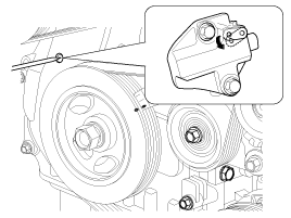
(2)
Check that the TDC marks (A) of the CVVT sprockets are in
straight line on the cylinder head surface as shown in the illustration.
If not, turn the crankshaft one revolution (360┬░).
3.
Mark the timing chains (A) corresponding to the timing marks of the CVVT sprockets.
4.
Turn the crankshaft pulley 15┬░ clockwise.
5.
Remove the service hole bolt (A) of the timing chain cover.
The bolt must not be reused once it has been assembled.
6.
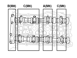
Remove the intake and exhaust camshaft bearing caps.
7.
Release the ratchet of the timing chain tensioner by pulling the link down using a thin rod.
8.
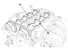
After loosening the timing chain, remove the exhaust CVVT
& camshaft assembly (A) and then the intake CVVT & camshaft
assembly (B).
When taking off the timing chain from the CVVT sprockets, hold the timing chain.
9.
Tie down timing chain so that it doesn''t move.
Be careful not to drop anything inside timing chain cover.
Installation
1.
Hold the timing chain, and place the intake CVVT & camshaft assembly.
2.
Place the exhaust CVVT & camshaft assembly after releasing the ratchet of the timing chain tensioner.
The timing marks of each CVVT sprocket should be matched with
timing marks (painted link) of timing chain when installing the timing
chain.
3.
Install the camshaft bearing caps in their proper locations.
Turn the crankshaft two turns in the operating direction
(clockwise), and then check that the TDC marks (A) of the CVVT sprockets
are in straight line on the cylinder head surface.
6.
Install the cylinder head cover. (Refer to Timing system in this group)
Disassembly
1.
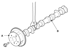
Disassemble the CVVT assembly (A) and camshaft (B).
When removing the CVVT assembly bolt, prevent the camshaft from rotating by using a wrench.
Reassembly
1.
Reassemble the CVVT assembly (A) and camshaft (B).
Tightening torque :
53.9 ~ 63.7N.m (5.5 ~ 6.5kgf.m, 39.7 ~ 47.0lb-ft)
When installing the CVVT assembly bolt, prevent the camshaft from rotating by using a wrench.
Valve Clearance Inspection And Adjustment
Inspect and adjust the valve clearance when the engine is
cold (Engine coolant temperature : 20┬░C (68┬░F)) and cylinder hea ...
Opening the hood
1.Pull the release lever to unlatch the hood. The hood should pop open slightly.
Open the hood after turning off the engine on a flat surface, shifting the shift
lever to the P(Park) position for ...
Closing the hood
1.Before closing the hood, check the following:
All filler caps in the engine compartment must be correctly installed.
Gloves, rags or any other combustible material must be removed from the
...
 Kia Sportage: Camshaft: Repair procedures


 Valve Clearance Adjustment
 Cylinder Head: Components and Components Location