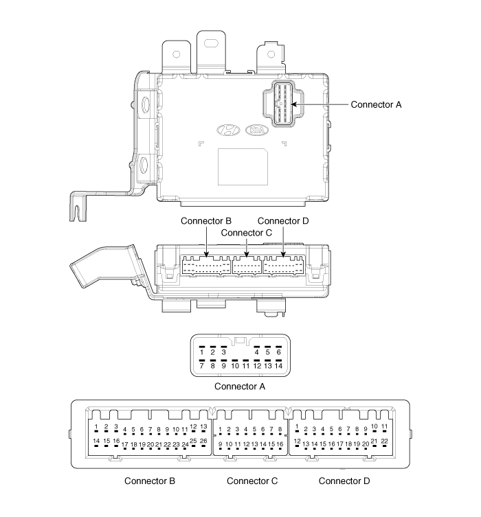
 Kia Sportage: Smart key unit: Components and Components Location
Third generation SL (2010ŌĆō2016) / Kia Sportage SL Service & Repair Manual / Body Electrical System / Smart key System / Smart key unit: Components and Components Location
| Components |

Connector Pin Information
| No | Connector A (14 Pin) | No | Connector B (26 Pin) | ||
| 1 | Ground 1 | 1 | - | 15 | L_Passenger lock button, L_Passenger toggle button |
| 2 | A_ACC | 2 | L_Driver lock button, L_Driver toggle button | 16 | - |
| 3 | A_IGN2 | 3 | - | 17 | - |
| 4 | A_IGN1 | 4 | - | 18 | - |
| 5 | VBAT_CPU | 5 | - | 19 | L_Fob input |
| 6 | VBAT_LOAD | 6 | L_SSB_Switch1 | 20 | F_RPM |
| 7 | Ground 2 | 7 | F_Wheel vehicle | 21 | L_Start Feedback |
| 8 | - | 8 | L_SSB_Switch2 | 22 | - |
| 9 | O_Exterior buzzer | 9 | - | 23 | - |
| 10 | O_ACC Relay | 10 | - | 24 | - |
| 11 | O_IGN1 Relay | 11 | - | 25 | - |
| 12 | O_IGN2 Relay | 12 | B_CAN_H | 26 | L_Tailgate Switch |
| 13 | O_Starter Relay | 13 | B_CAN_L | ? | ? |
| 14 | - | 14 | - | ||
Connector Pin Information
| No | Connector C (16 Pin) | No | Connector D (22 Pin) |
| 1 | C_CAN_L | 1 | Immobilizer warning lamp |
| 2 | C_CAN_H | 2 | O_SSB_LED_AMBER |
| 3 | - | 3 | O_SSB_illumination power |
| 4 | O_Holder illumination | 4 | O_Interior antenna 2 ground |
| 5 | - | 5 | O_Interior antenna 1 ground |
| 6 | Diagnostic K | 6 | - |
| 7 | L_Brake switch | 7 | - |
| 8 | Immobilizer data | 8 | O_Interior antenna 3 power |
| 9 | RF_COM | 9 | O_Bumper antenna power |
| 10 | EMS_COM | 10 | O_Passenger side antenna power |
| 11 | - | 11 | O_Driver side antenna power |
| 12 | - | 12 | - |
| 13 | L_Stop lamp fuse | 13 | O_SSB_LED_Blue |
| 14 | - | 14 | O_SSB_illumination ground |
| 15 | L_P shift, L_Clutch switch | 15 | O_Interior antenna 2 power |
| 16 | Immobilizer clock | 16 | O_Interior antenna 1 power |
| 17 | - | ||
| 18 | - | ||
| 19 | O_Interior antenna 3 ground | ||
| 20 | O_Bumper antenna ground | ||
| 21 | O_Passenger side antenna ground | ||
| 22 | O_Driver side antenna ground |
 Smart key: Repair procedures
Smart Key
Smart Key Code Saving
1.
Connect the DLC cable of GDS to the data link connector (16 pins) in driver side crash pad lower panel, turn the power on GDS.
2.
Select the vehicle model a ...
 Smart key unit: Schematic Diagrams
Circuit Diagram
...
Other Information:
Valve Body: Description and Operation
Description
The valve body is essential to automatic transaxle control
and consists of various valves used to control the oil feed from the oil
pump. Specifically, these valves consist of press ...
Schematic Diagrams
Schematic Diagram
...
Categories
- Home
- Kia Sportage QL (2015-2019) Owners Manual
- Kia Sportage QL (2015-2019) Service Manual
- Kia Sportage SL 2010-2016 Owners Manual
- Kia Sportage SL 2010-2016 Service Manual
Copyright ® www.kispmanual.com 2014-2026
