
 Kia Sportage: PDM Relay Box: Repair procedures
Third generation SL (2010–2016) / Kia Sportage SL Service & Repair Manual / Body Electrical System / Fuses And Relays / PDM Relay Box: Repair procedures
| Removal |
PDM Relay
| 1. |
Disconnect the negative (-) battery terminal. |
| 2. |
Remove the floor console assembly.
(Refer to BD group - "Console") |
| 3. |
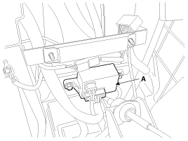
Remove the PDM relay box (A) after loosening the bolts (2EA) and disconnecting the connector.
|
| Installation |
| 1. |
Install the PDM relay box. |
| 2. |
Install the floor console assembly. |
| 3. |
Connect the battery (-) cable. |
| Inspection |
IG2 Relay
Check for continuity between the terminals.
| 1. |
There should be continuity between the No.1 and No.2
terminals in the B connector when power and ground are connected to the
No.3 and No.4 terminals in the A connector. |
| 2. |
There should be no continuity between the No.1 in the B and No.2 terminals in the B terminals when power is disconnected. |
IG1 Relay
Check for continuity between the terminals.
| 1. |
There should be continuity between the No.7 and No.8
terminals in the A connector when power and ground are connected to the
No.3 and No.10 terminals in the A connector. |
| 2. |
There should be no continuity between the No.7 in the A and No.8 terminals in the A terminals when power is disconnected. |
ACC Relays
Check for continuity between the terminals.
| 1. |
There should be continuity between the No.7 and No.6
terminals in the A connector when power and ground are connected to the
No.1 and No.3 terminals in the A connector. |
| 2. |
There should be no continuity between the No.7 in the A and No.6 terminals in the A terminals when power is disconnected. |
 PDM Relay Box: Description and Operation
Description
The PDM relay (A) is united with IG1, IG2 and ACC relays and installed in the lower center fascia panel. ...

Other Information:
Special Service Tools
Special Service Tools
Tool (Number and name)IllustrationUseAlternator pulley remover wrench(09373-27000)Removal and installation of alternator pulley
...
Heated Oxygen Sensor (HO2S): Repair procedures
Inspection
1.
Turn the ignition switch OFF.
2.
Disconnect the HO2S connector.
3.
Measure resistance between the HO2S terminals 4 and 5 [B1/S1].
4.
Measure resistance between the HO2S t ...
Categories
- Home
- Kia Sportage QL (2015-2019) Owners Manual
- Kia Sportage QL (2015-2019) Service Manual
- Kia Sportage SL 2010-2016 Owners Manual
- Kia Sportage SL 2010-2016 Service Manual

Copyright © www.kispmanual.com 2014-2026