 Kia Sportage: Front Cross Member: Repair procedures
Third generation SL (2010–2016) / Kia Sportage SL Service & Repair Manual / Suspension System / Front Suspension System / Front Cross Member: Repair procedures
| Replacement |
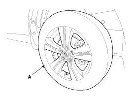
| 1. |
Remove the front wheel & tire.
|

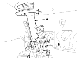
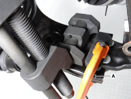
| 2. |
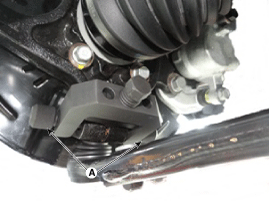
Disconnect the stabilizer link (B) from the front strut assembly (A) after loosening the nut.
|
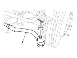
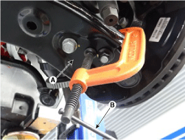
| 3. |
Remove the split pin and castle nut and then disconnect the tie-rod end (A) from the front knuckle.
|
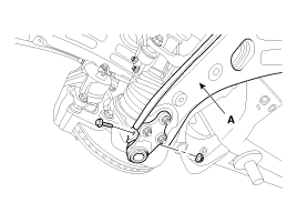
| 4. |
Loosen the bolt & nut and then remove the lower arm (A).
|
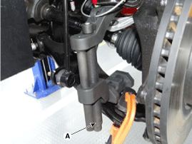
| 5. |
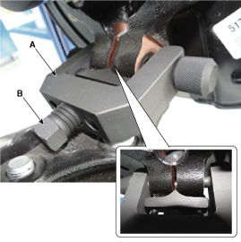
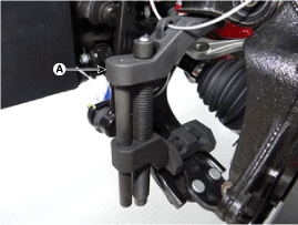
Remove the front lower arm from the front knuckle using the SST (0K545-A9100).
|

| 6. |
Remove the dust cover. |
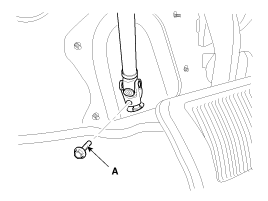
| 7. |
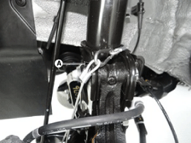
Loosen the bolt (A) and then disconnect the universal joint assembly from the pinion of the steering gear box.
|
| 8. |
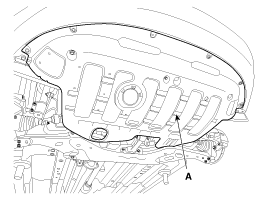
Remove the under cover (A).
|
| 9. |
Loosen the bolt (A) & nut (B) and then remove the roll rod stopper.
|
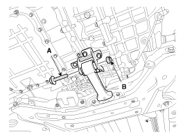
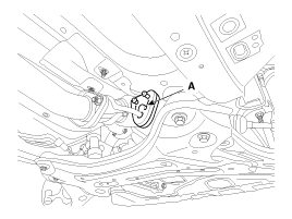
| 10. |
Disconnect the muffler rubber hanger (A).
|
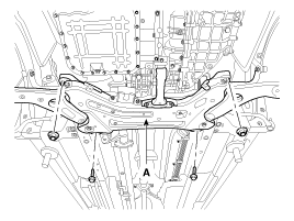
| 11. |
Loosen the bolts & nuts and then remove the sub frame.
|
| 12. |
Remove the front lower arm.
(Refer to Front lower arm) |
| 13. |
Remove the front stabilizer.
(Refer to Front stabilizer) |
| 14. |
Remove the steering gearbox.
(Refer to "Steering Gearbox" in ST group ) |
| 15. |
Installation is the reverse of removal. |
 Front Stabilizer Bar: Repair procedures
Replacement
1.
Remove the front wheel & tire.
Tightening torque :
88.3 ~ 107.9N.m (9.0 ~ 11.0kgf.m, 65.1 ~ 79.6lb-ft)
Be careful not to damage to the hub ...

Other Information:
Defroster
CAUTION - Conductors
To prevent damage to the conductors bonded to the inside surface of the rear
window, never use sharp instruments or window cleaners containing abrasives to clean
the wind ...
TPMS Sensor: Description and Operation
Description
1.
Mode
(1)
Normal Fixed Base State
•
Sensor transmissions continue at the Low Line (Base)
configuration defined rates until the state is either changed by LF
command or ...
Categories
- Home
- Kia Sportage QL (2015-2019) Owners Manual
- Kia Sportage QL (2015-2019) Service Manual
- Kia Sportage SL 2010-2016 Owners Manual
- Kia Sportage SL 2010-2016 Service Manual
Copyright © www.kispmanual.com 2014-2024