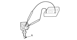
Connect a circuit tester to the connector of stop lamp
switch, and check whether or not there is continuity when the plunger of
the stop lamp switch is pushed in and when it is released.
(2)
The stop lamp switch is in good condition if there is no continuity when plunger(A) is pushed.
Installation
1.
Installation is the reverse of removal.
•
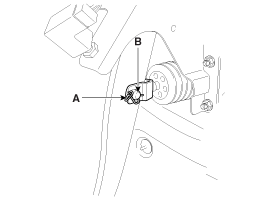
Before installing the pin, apply the grease to the clevis pin.
•
Use a new snap pin whenever installing.
2.
Adjust the brake pedal height and free play.
3.
Check the brake pedal operation.
Adjustment
Brake Pedal Height and Free Play
1.
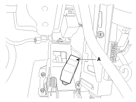
Disconnect the stop lamp switch connector (A) and loosen the stop lamp switch lock nut.
2.
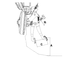
Adjust the brake pedal height (A) as illustration below.
Pedal height (A) : 165 mm (6.50 in)
Full stroke (C) : 135 mm (5.31 in)
3.
Adjust the stop lamp switch clearance (B) and brake pedal free play.
Air cleaner
Filter replacement
It must be replaced when necessary, and should not be washed.
You can clean the filter when inspecting the air cleaner element.
Clean the filter by using compressed air.
Repla ...

 Kia Sportage: Brake Pedal: Repair procedures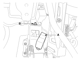

 Brake Pedal: Components and Components Location
 Front Disc Brake: Components and Components Location