Kia Sportage: Troubleshooting - Tire Pressure Monitoring System - Suspension System - Kia Sportage SL Service & Repair ManualKia Sportage: Troubleshooting

Third generation SL (2010–2016) / Kia Sportage SL Service & Repair Manual / Suspension System / Tire Pressure Monitoring System / Troubleshooting

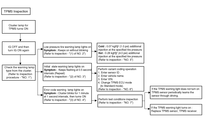
TPMS Inspection method

Inspection
   
Find the inspection number by referring to the table above.
The following content is irrelevant of the inspection procedure.
1.
Warning lamp types
Keeps on without blinking : Low pressure tire warning lamp
Flashes at 0.5 second intervals constantly : Initial state warning lamp
Cluster blinks for 1 minute at 1 second intervals, then turns ON : Error code warning lamp
   
Turn IG OFF and then IG ON again to check the warning light type.
2.
(1) Check the warning lamp state.
Check the vehicle warning lamp state.
Check if the warning lamp state is caused by tire low pressure.

Symptom : Keeps on without blinking
3.
(2) Check the warning lamp state.
Check the vehicle warning lamp state.
Check if the warning lamp state is caused by the initial state (virgin mode) of TPMS receiver.

Symptom : Flashes at 0.5 second intervals constantly.
4.
(3) Check the warning lamp state.
Check the vehicle warning lamp state.
Check if the warning lamp state is caused by error code (TPMS receiver & TPMS sensor failure).
Symptom : Cluster blinks for 1 minute at 1 second intervals, then turns ON.
5.
Low tire pressure warning lamp
Cold : Vehicle kept for more than 60 minutes after stopping.
> 0.07 kgf/cm? (1.0 psi) additional injection at the specified tire pressure.
Hot : Driven vehicle
> 0.28 kgf/cm? (4.0 psi) additional injection at the specified tire pressure.
   
In case the warning lamp fails to turn OFF after injecting tire pressure, disconnect the GDS and drive less than 1 km at 25 km/h.
6.
Inspect initial state warning lamp
A.
TPMS warning lamp
(1) Check the TPMS warning lamp status.
(2)Flashes at 0.5 second intervals constantly. -> Initial state warning lamp
   
Turn IG OFF and then IG ON again to check the warning lamp type.
B.
Items to check in case of blinking warning lamp
(1). Enter sensor ID.
(Refer to TPMS Receiver - "Repair procedures")
(2). Enter vehicle name.
(Refer to TPMS Receiver - "Repair procedures")
(3). Enter VIN.
(Refer to TPMS Receiver - "Repair procedures")
(4). Change TPMS ECU mode (to Standard mode).
7.
DTC checklist for performance test.
List
symptoms
Inspection items
Detailed checklist
Component/parts
C1312(FL)
C1313(FR)
C1314(RL)
C1315(RR)
TPMS sensor receive error.
Sensor RF transmission state
Confirm sensor RF transmission
Check sensor DTC
Inspect Ssnsor battery
TPMS Sensor
Vehicle electronic units noise
Vehicle operating conditions
C1332(FL)
C1333(FR)
C1334(RL)
C1335(RR)
Sensor internal failure
Inspect sensor RF transmission
Sensor battery voltage
Check sensor RF transmission
Check sensor battery (GDS)
TPMS Sensor
C1662
Auto learning failure
Sensor RF transmission state
Inspect EMS vehicle speed (VS)
Inspect vehicle noise
Confirm sensor RF transmission
Inspect sensor battery
Inspect EMS vehicle speed (VS)
Inspect vehicle electronic unit noise
TPMS Sensor
Vehicle electronic units noise
Vehicle operating condition
EMS vehicle speed signal
C1663
Auto learning failure
Sensor RF transmission state
Inspect EMS vehicle speed (VS)
Inspect vehicle noise
Confirm sensor RF transmission
Inspect sensor battery
Inspect EMS vehicle speed (VS)
Inspect vehicle electronic unit noise
TPMS Sensor
Vehicle electronic units noise
Vehicle operating condition
EMS vehicle speed signal

   
Be sure to check DTC.
(Refer to DTC manual - "Tire Pressure Monitoring")
If the TPMS warning light does not turn on : TPMS sensor periodically learns the sensor through driving.
If the TPMS warning light turns on : Replace TPMS sensor, TPMS receiver.
Description and Operation
Description TREAD Lamp – Tire Under Inflation / Leak Warning. 1. Turn on condition • When tire pressure is below allowed threshold • When rapid leak is detected by the ...

TPMS Sensor: Description and Operation
Description 1. Mode (1) Normal Fixed Base State • Sensor transmissions continue at the Low Line (Base) configuration defined rates until the state is either changed by LF command or ...

Other Information:

AUX(Auxiliary) Jack: Description and Operation
Description The AUX, iPod and USB JACK on the center console is for customers who like to listen to external portable music players like the MP3, iPod, earphone, USB memory stick, CD player and ...

Description and Operation
Description Ignition timing is controlled by the electronic control ignition timing system. The standard reference ignition timing data for the engine operating conditions are preprogrammed in ...

Categories


Copyright © www.kispmanual.com 2014-2024