 Kia Sportage: Cruise Control Switch: Repair procedures
Third generation SL (2010ŌĆō2016) / Kia Sportage SL Service & Repair Manual / Engine Electrical System / Cruise Control System / Cruise Control Switch: Repair procedures
| Removal and Installation |
| 1. |
Disconnect the battery (-) terminal.
|
| 2. |
Remove the air-bag module from the steering wheel. ( Refer to RT group) |
| 3. |
Remove the steering wheel. (Refer to ST group) |
| 4. |
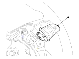
Remove the cruise control switch (A) after unfastening the 2 screws and disconnecting the switch connector.
|
| 5. |
Installation is reverse order of removal. |
| Inspection |
Measuring Resistance
| 1. |
Disconnect the cruise control switch connector from the control switch.
|
| 2. |
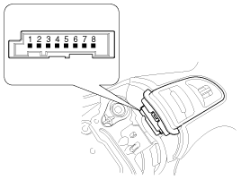
Measure resistance between terminals on the control switch when each function switch is ON (switch is depressed).
|
| 3. |
If not within specification, replace switch. |
Measuring Voltage
| 1. |
Connect the cruise control switch connector to the control switch. |
| 2. |
Measure voltage between terminals on the harness side connector when each function switch is ON (switch is depressed).
|
| 3. |
If not within specification, inspect the control switch resistance.
The measuring resistance value is not within specification, replace the switch and measure the voltage again. |
| 4. |
If resistance is OK but, measuring voltage is not within
specification, inspect the wiring harness and connectors between the
switch and the ECM. |
 Cruise Control Switch: Schematic Diagrams
Circuit Diagram
...
Other Information:
Components and Components Location
Component Location
1. Panoramaroof2. Panoramaroof switch3. Panoramaroof motor & controller
Components
1. Panoramaroof frame assembly2. Panoramaroof impact cross member assembly3. Panora ...
Front Driveshaft: Repair procedures
Replacement
1.
Loosen the wheel nuts slightly.
Raise the vehicle, and make sure it is securely supported.
2.
Remove the front wheel and tire (A) from front hub.
Tightening torque :
88.3 ~ ...
Categories
- Home
- Kia Sportage QL (2015-2019) Owners Manual
- Kia Sportage QL (2015-2019) Service Manual
- Kia Sportage SL 2010-2016 Owners Manual
- Kia Sportage SL 2010-2016 Service Manual
Copyright ® www.kispmanual.com 2014-2026


