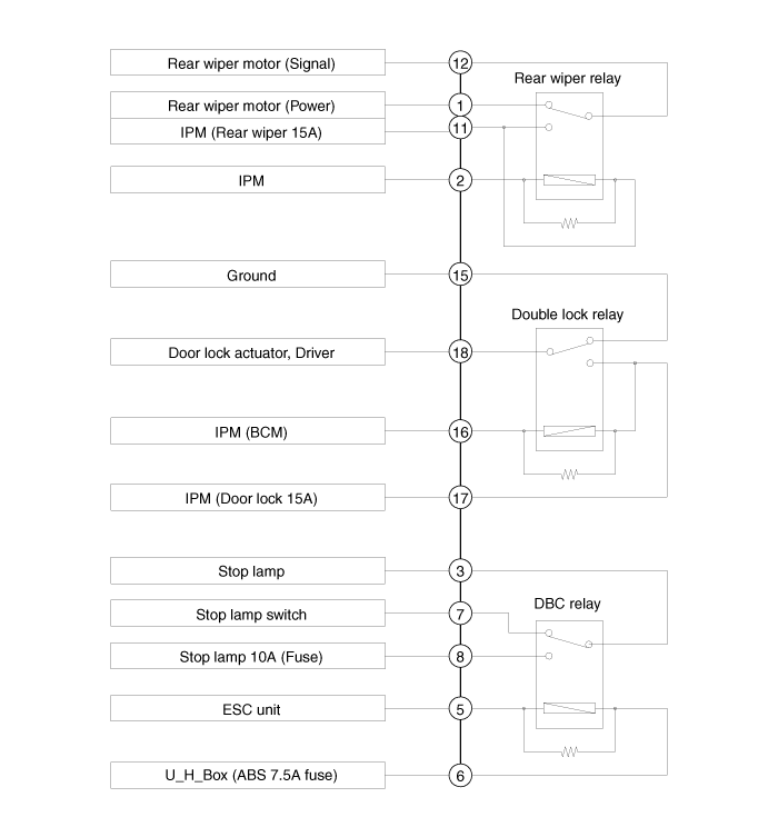
 Kia Sportage: ICM (Integrated Circuit Module) Relay Box: Schematic Diagrams
Third generation SL (2010ŌĆō2016) / Kia Sportage SL Service & Repair Manual / Body Electrical System / Fuses And Relays / ICM (Integrated Circuit Module) Relay Box: Schematic Diagrams
| Schematic Diagram |

 ICM (Integrated Circuit Module) Relay Box: Components and Components Location
Component
Pin Information
NoConnector ANoConnector A1Rear wiper motor (Power)11IPM (Rear wiper 15A)2IPM12Rear wiper motor (Signal)3Stop lamp13-4-14-5ESC unit15GND6U_H_Box (ABS 7.5A fuse)16IPM (B ...
 ICM (Integrated Circuit Module) Relay Box: Description and Operation
Description
The ICM relay (A) is united with rear wiper relay, and DBC relay which installed inside the lower crash pad. ...
Other Information:
Components and Components Location
Component Location
1. Rear glass defogger relay2. Rear glass defogger switch3. Rear glass defogger
...
Front Fog Lamps: Repair procedures
Inspection
Front Fog Lamp Switch
1.
With the fog lamp switch in each position, make sure that
continuity exists between the terminals below. If continuity is not as
specified, replace the mul ...
Categories
- Home
- Kia Sportage QL (2015-2019) Owners Manual
- Kia Sportage QL (2015-2019) Service Manual
- Kia Sportage SL 2010-2016 Owners Manual
- Kia Sportage SL 2010-2016 Service Manual
Copyright ® www.kispmanual.com 2014-2026
