 Kia Sportage: Instrument Cluster: Schematic Diagrams
Third generation SL (2010ŌĆō2016) / Kia Sportage SL Service & Repair Manual / Body Electrical System / Indicators And Gauges / Instrument Cluster: Schematic Diagrams
| Circuit Diagram (1) |
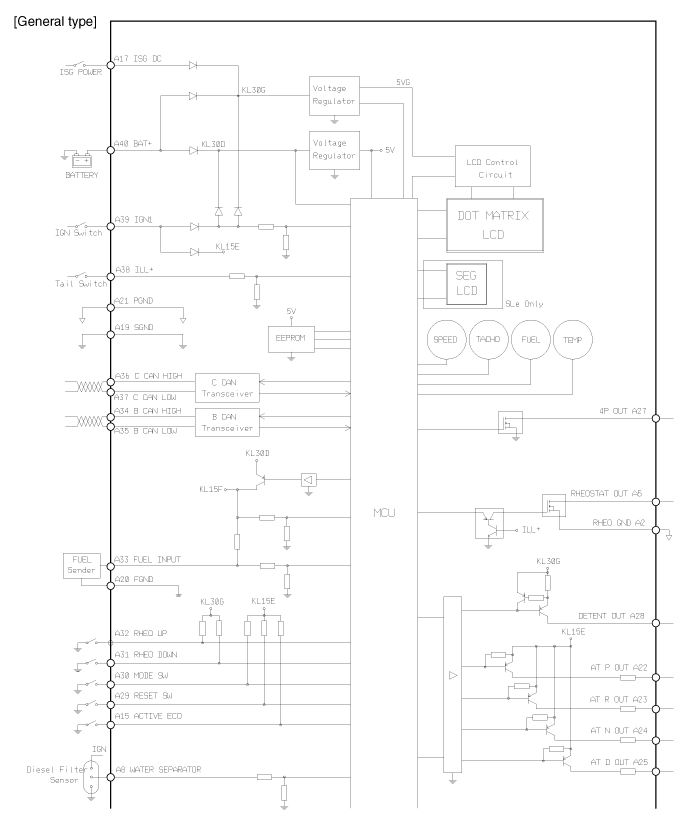
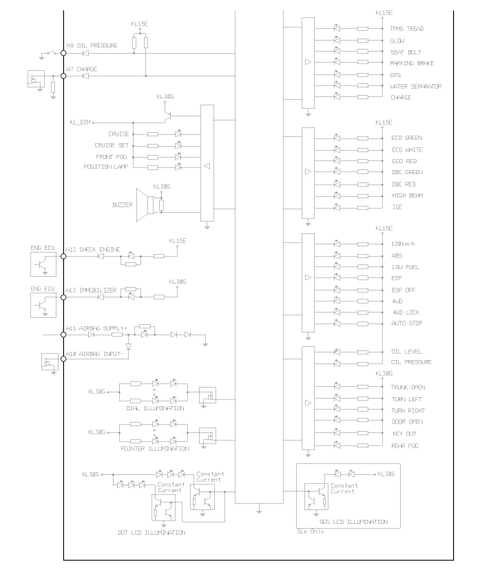
| Circuit Diagram (2) |
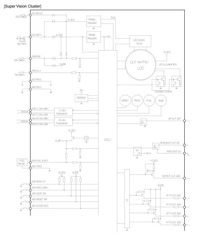
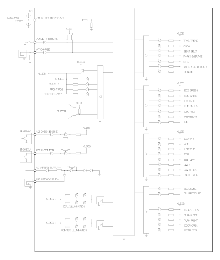
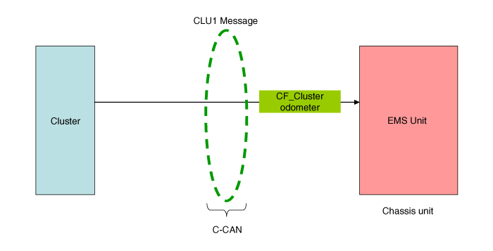
| CLU1 message signal flow (B > C CAN gateway) |
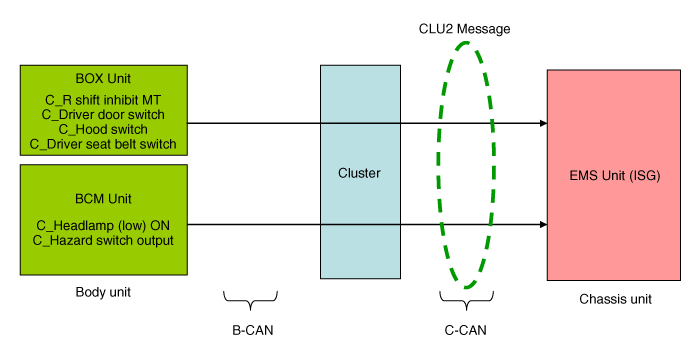
| CLU2 message signal flow (B > C CAN gateway) |
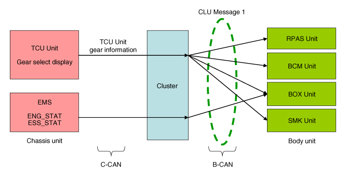
| CLU message 1 signal flow (C > B CAN gateway) |
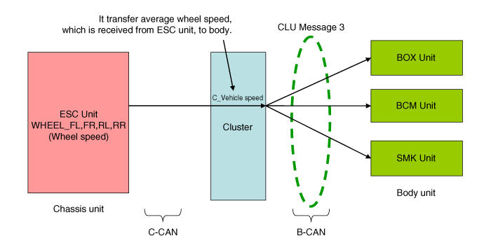
| CLU message 3 signal flow (C > B CAN gateway) |
 Instrument Cluster: Components and Components Location
Components
...
 Instrument Cluster: Description and Operation
Description
ECO driving system
This system is designed to encourage eco-driving by providing real-time feedback to the driver.
The ECO indicator light assists you to drive in the most economical ...
Other Information:
Front Wheel Transfer Assembly: Repair procedures
Removal
It is not recommended to overhaul the transfer assembly
because a special three-dimensional measuring instrument is required to
determine the sizes of the t ...
Alternator: Components and Components Location
Components
1. Pulley2. Front bracket3. Front bearing4. Rotor 5. Rear bearing 6. Rear bracket7. Through bolt8. Regulator assembly9. Regulator bolt10. Rear cover
...
Categories
- Home
- Kia Sportage QL (2015-2019) Owners Manual
- Kia Sportage QL (2015-2019) Service Manual
- Kia Sportage SL 2010-2016 Owners Manual
- Kia Sportage SL 2010-2016 Service Manual
Copyright ® www.kispmanual.com 2014-2026
