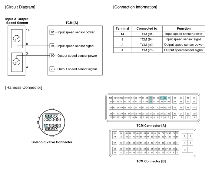
 Kia Sportage: Output Speed Sensor: Schematic Diagrams
Third generation SL (2010ŌĆō2016) / Kia Sportage SL Service & Repair Manual / Automatic Transaxle System / Automatic Transaxle Control System / Output Speed Sensor: Schematic Diagrams
| Circuit Diagram |

 Output Speed Sensor: Specifications
Specifications
? Type: Hall effect sensor
Operation condition (┬░C)┬░F(-40~150) -40~302Air gap (mm)in.(0.25~0.70) 0.0098~0.0276Output voltage (V)High1.18 ~ 1.68Low0.59 ~ 0.84
...
 Output Speed Sensor: Troubleshooting
Signal Waveform
Fig 1) Input/Output speed sensor at low speed
Fig 2) Input/Output speed sensor at high speed ...
Other Information:
Rear Cross Member: Repair procedures
Replacement
1.
Remove the rear wheel & tire.
Tightening torque :
88.3 ~ 107.9N.m (9.0 ~ 11.0kgf.m, 65.1 ~ 79.6lb-ft)
Be careful not to damage to the hub bo ...
Balance Shaft & Oil Pump: Components and Components Location
Components
1. Balance shaft & oil pump assembly2. Balance shaft chain tensioner3. Balance shaft chain4. Balance shaft chain sprocket5. Balance shaft chain guide6. Balance shaft chain tensione ...
Categories
- Home
- Kia Sportage QL (2015-2019) Owners Manual
- Kia Sportage QL (2015-2019) Service Manual
- Kia Sportage SL 2010-2016 Owners Manual
- Kia Sportage SL 2010-2016 Service Manual
Copyright ® www.kispmanual.com 2014-2026
