 Kia Sportage: Power Door Lock Actuators: Repair procedures
Third generation SL (2010ŌĆō2016) / Kia Sportage SL Service & Repair Manual / Body Electrical System / Power Door Locks / Power Door Lock Actuators: Repair procedures
| Inspection |
Front Door Lock Actuator
| 1. |
Remove the front door trim.
(Refer to the BD group - "Front door") |
| 2. |
Remove the front door module.
(Refer to the BD group - "Front door") |
| 3. |
Disconnect the connectors from the actuator.
|
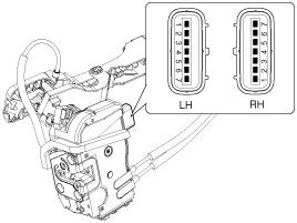
| 4. |
Check actuator operation by connecting power and ground
according to the table. To prevent damage to the actuator, apply battery
voltage only momentarily.
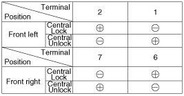
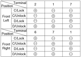
[Central Lock]
[Double Lock]
|
Rear Door Lock Actuator
| 1. |
Remove the rear door trim.
(Refer to the BD group - "Rear door") |
| 2. |
Remove the rear door module.
(Refer to the BD group - "Rear door") |
| 3. |
Disconnect the connectors from the actuator.
|
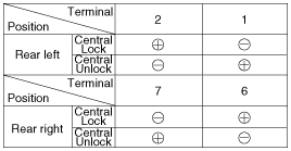
| 4. |
Check actuator operation by connecting power and ground
according to the table. To prevent damage to the actuator, apply battery
voltage only momentarily.
[Central Lock]
[Double Lock]
|
Tailgate Lock Actuator Inspection
| 1. |
Remove the tailgate trim.
(Refer to the BD group - "Tailgate") |
| 2. |
Disconnect the 4P connector from the actuator.
|
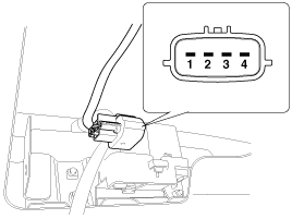
| 3. |
Check actuator operation by connecting power and ground
according to the table. To prevent damage to the actuator, apply battery
voltage only momentarily.
|
Front Door Lock Switch
| 1. |
Remove the front door trim.
(Refer to the BD group - "Front door") |
| 2. |
Remove the front door module.
(Refer to the BD group - "Front door") |
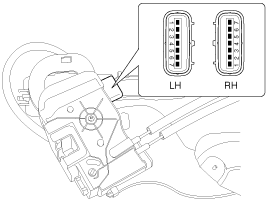
| 3. |
Disconnect the connectors from the actuator.
|
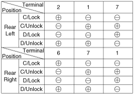
| 4. |
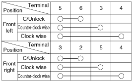
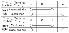
Check for continuity between the terminals in each switch position when inserting the key into the door according to the table.
[Central Lock]
[Double Lock]
|
Rear Door Lock Switch
| 1. |
Remove the rear door trim.
(Refer to the BD group - "Rear door") |
| 2. |
Remove the rear door module.
(Refer to the BD group - "Rear door") |
| 3. |
Disconnect the connectors from the actuator.
|
| 4. |
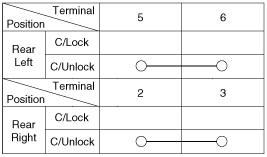
Check for continuity between the terminals in each switch position according to the table.
[Central Lock]
|
Tailgate Switch
| 1. |
Remove the tailgate trim.
(Refer to the BD group - "Tailgate") |
| 2. |
Disconnect the 4P connector from the actuator.
|
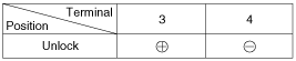
| 3. |
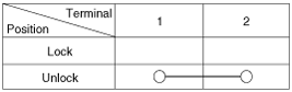
Check for continuity between the terminals in each switch position according to the table.
|
 Components and Components Location
Component Location
1. Driver power window switch2. Assist power window switch3. SJB (Smart Junction Box)4. Door lock switch5. Tailgate lock actuator & switch6. Front door lock actuator & ...
 Power Door Lock Switch: Repair procedures
Inspection
Driver Power Door Lock Switch
1.
Disconnect the negative battery terminal.
2.
Remove the front door trim.
(Refer to the BD group - "Front door")
3.
Disconnect the switch conne ...
Other Information:
Description and Operation
Description
The hydraulic system consists of oil, an oil filter, an oil pump, and a valve body (valves and solenoid valves).
The oil pump is powered by the engine. ATF passes through the oil filt ...
Intake Actuator: Description and Operation
Description
1.
The intake actuator is located at the blower unit.
2.
It regulates the intake door by signal from control unit.
3.
Pressing the intake selection switch will shift between re ...
Categories
- Home
- Kia Sportage QL (2015-2019) Owners Manual
- Kia Sportage QL (2015-2019) Service Manual
- Kia Sportage SL 2010-2016 Owners Manual
- Kia Sportage SL 2010-2016 Service Manual

Copyright ® www.kispmanual.com 2014-2026