 Kia Sportage: Telemetics Unit (TMU): Components and Components Location
Third generation SL (2010ŌĆō2016) / Kia Sportage SL Service & Repair Manual / Body Electrical System / MTS System / Telemetics Unit (TMU): Components and Components Location
| Component |
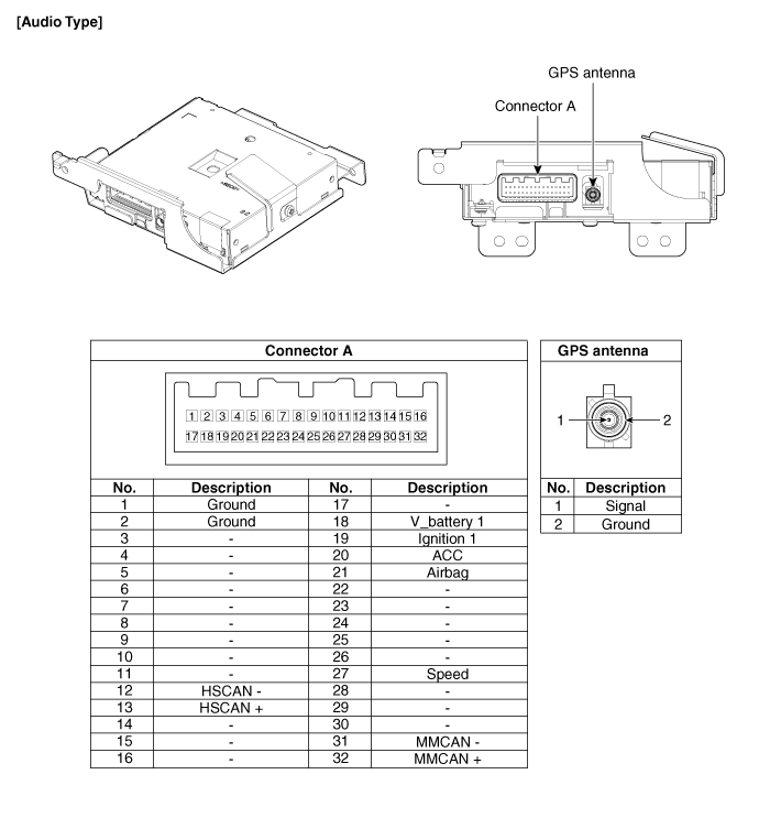
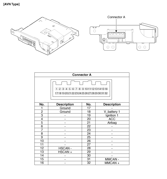
Connector Pin Specification
| No. | Pin Name | Type | From | To | Description (Wiring Spec.) |
| 1 | GND | DC Ground | TMU | Battery | Connected to battery ground |
| 2 | GND | DC Ground | TMU | Battery | Connected to battery ground |
| 3 | - | - | - | - | - |
| 4 | - | - | - | - | - |
| 5 | - | - | - | - | - |
| 6 | - | - | - | - | - |
| 7 | - | - | - | - | - |
| 8 | - | - | - | - | - |
| 9 | - | - | - | - | - |
| 10 | - | - | - | - | - |
| 11 | - | - | - | - | - |
| 12 | HS CAN (-) | Data I/O | BUS | BUS | High Speed CAN bus low |
| 13 | HS CAN (+) | Data I/O | BUS | BUS | High Speed CAN bus high |
| 14 | - | - | - | - | - |
| 15 | - | - | - | - | - |
| 16 | - | - | - | - | - |
| 17 | - | - | - | - | - |
| 18 | V battery 1 | DC Input | Battery | TMU | DC level input from battery Supply power to TMU |
| 19 | Ignition 1 | Data Input | Junction Box | TMU | Vehicle Key mode status |
| 20 | ACC | Data Input | Junction Box | TMU | Vehicle Key mode status |
| 21 | Airbag | Data Input | ACU | TMU | Airbag status data from ACU |
| 22 | - | - | - | - | - |
| 23 | - | - | - | - | - |
| 24 | - | - | - | - | - |
| 25 | - | - | - | - | - |
| 26 | - | - | - | - | - |
| 27 | Speed | Data Input | - | TMU | GPS Calibration (UVO ONLY) |
| 28 | - | - | - | - | - |
| 29 | - | - | - | - | - |
| 30 | - | - | - | - | - |
| 31 | MM CAN (-) | Data I/O | BUS | BUS | Low Speed CAN bus low |
| 32 | MM CAN (+) | Data I/O | BUS | BUS | Low Speed CAN bus high |
 Description and Operation
Description
The Vehicle Information System is a Telematics service that
ensures comfortable and enjoyable driving by providing safety, security,
and vehicle diagnostic information, with the opt ...
 Telemetics Unit (TMU): Repair procedures
Removal
ŌĆó
Take care not to scratch the crash pad and related parts.
1.
Disconnect the negative (-) battery terminal.
2.
Remove the crash pad garnis ...
Other Information:
Instrument panel overview
1. Lighting controls / Turn signals
2. Steering wheel audio controls
3. Instrument cluster
4. Horn
5. DriverŌĆÖs front air bag
6. Cruise controls
7. Wiper/Washer switch
8. ENGINE START/STOP b ...
Parking Brake Assembly: Components and Components Location
Components (1)
1. Parking brake pedal assembly2. Front parking brake cable (Foot type only)3. Equalizer assembly4. Rear parking brake cable5. Parking brake lever assembly
Components (2)
1. ...
Categories
- Home
- Kia Sportage QL (2015-2019) Owners Manual
- Kia Sportage QL (2015-2019) Service Manual
- Kia Sportage SL 2010-2016 Owners Manual
- Kia Sportage SL 2010-2016 Service Manual

Copyright ® www.kispmanual.com 2014-2026