 Kia Sportage: Mode Control Actuator: Repair procedures
Third generation SL (2010ŌĆō2016) / Kia Sportage SL Service & Repair Manual / Heating,Ventilation, Air Conditioning / Heater / Mode Control Actuator: Repair procedures
| Inspection |
| 1. |
Ignition "OFFŌĆØ |
| 2. |
Disconnect the connector of mode control actuator. |
| 3. |
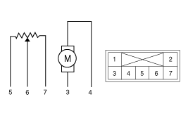
Verify that the mode control actuator operates to the defrost
mode when connecting 12V to the terminal 3and grounding terminal 4. |
| 4. |
Verify that the mode control actuator operates to the vent mode when connecting in the reverse.
|
| 5. |
Check the voltage between terminals 5 and 6.
It will feedback current position of actuator to controls. |
| 6. |
If the measured voltage is not specification, substitute with a known-good mode control actuator and check for proper operation. |
| 7. |
If the problem is corrected, replace the mode control actuator. |
| Replacement |
| 1. |
Disconnect the negative (-) battery terminal. |
| 2. |
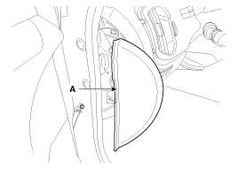
Remove the crash pad left side cover (A).
|
| 3. |
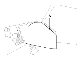
Remove the left extension cover(A).
|
| 4. |
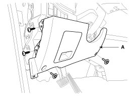
Remove the crash pad lower cover (A).
|
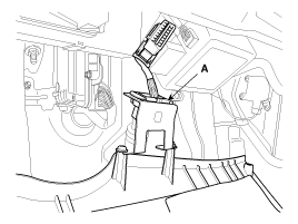
| 5. |
Disconnect the diagnosis connector (A).
|
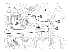
| 6. |
Remove the reinforcing panel (A).
|
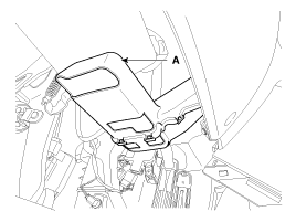
| 7. |
Remove the left shower duct (A).
|
| 8. |
Remove the BCM.
(Refer to BE group - "BCM") |
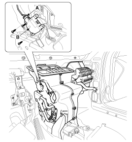
| 9. |
Disconnect the mode control actuator connector (A). |
| 10. |
Loosen the mounting screw and then remove the mode control actuator (B).
|
| 11. |
Installation is the reverse order of removal. |
 Mode Control Actuator: Description and Operation
Description
The mode control actuator is located at the heater unit.
It adjusts position of mode door by operating mode control
actuator based on signal of A/C control unit. Pressing mode select ...
 Blower
...
Other Information:
4WD ECU: Description and Operation
Description
4WD ECU processes signals from various sensors and determines
the current road and driving conditions. The ECU then utilizes this
information to implement precision control over the ...
Fuel Tank: Repair procedures
Removal
1.
Release the residual pressure in fuel line (Refer to the Fuel
Delivery System - Repair Procedures - "Release Residual Pressure in
Fuel Line").
2.
Remove the rear seat cushion (R ...
Categories
- Home
- Kia Sportage QL (2015-2019) Owners Manual
- Kia Sportage QL (2015-2019) Service Manual
- Kia Sportage SL 2010-2016 Owners Manual
- Kia Sportage SL 2010-2016 Service Manual
Copyright ® www.kispmanual.com 2014-2026

