 Kia Sportage: Description and Operation
Third generation SL (2010ŌĆō2016) / Kia Sportage SL Service & Repair Manual / Engine Electrical System / Charging System / Description and Operation
| Description |
The charging system includes a battery, an alternator with a built-in regulator, and the charging indicator light and wire.
The Alternator has built-in diodes, each rectifying AC current to DC current.
Therefore, DC current appears at alternator "B" terminal.
In addition, the charging voltage of this alternator is regulated by the ECM.
The main components of the alternator are the rotor, stator,
rectifier, capacitor brushes, bearings and V-ribbed belt pulley. The
brush holder contains a built-in electronic voltage regulator.
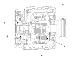
1. Brush
2. Dirve belt pulley
3. Rotor
4. Stator
5. Rectifier
Alternator Management System (AMS)
Alternator management system controls the charging voltage
set point in order to improve fuel economy, manage alternator load under
various operating conditions, keep the battery charged, and protect the
battery from over-charging. ECM controls generating voltage by duty
cycle (charging control, discharging control, normal control) based on
the battery conditions and vehicle operating conditions.
The system conducts discharging control when accelerating a
vehicle. Vehicle reduces an alternator load and consumes an electric
power form a battery.
The system conducts charging control when decelerating a vehicle. Vehicle increases an alternator load and charges a battery.
 Charging System
...
 Repair procedures
On-vehicle Inspection
ŌĆó
Check that the battery cables are connected to the correct terminals.
ŌĆó
Disconnect the battery cables when the battery is g ...
Other Information:
General Information
General
1.
Basically, all measurements in this manual are taken with a tracking gauge.
2.
When a measuring tape is used, check to be sure there is no elongation, twisting or bending.
3.
...
Intake Actuator: Description and Operation
Description
1.
The intake actuator is located at the blower unit.
2.
It regulates the intake door by signal from control unit.
3.
Pressing the intake selection switch will shift between re ...
Categories
- Home
- Kia Sportage QL (2015-2019) Owners Manual
- Kia Sportage QL (2015-2019) Service Manual
- Kia Sportage SL 2010-2016 Owners Manual
- Kia Sportage SL 2010-2016 Service Manual

Copyright ® www.kispmanual.com 2014-2026