 Kia Sportage: Timing Chain: Repair procedures
Third generation SL (2010ŌĆō2016) / Kia Sportage SL Service & Repair Manual / Engine Mechanical System / Timing System / Timing Chain: Repair procedures
| Removal |
|

Mark all wiring and hoses to avoid misconnection. |

In case of removing the high pressure fuel pump, high
pressure fuel pipe, delivery pipe, and injector, there may be injury
caused by leakage of the high pressure fuel. So donŌĆÖt do any repair
work right after engine stops. |

| 1. |
Remove the engine cover. |
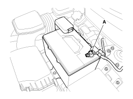
| 2. |
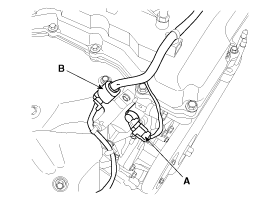
Disconnect the battery negative terminal (A).
|
| 3. |
Remove the air cleaner assembly.
|
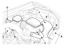
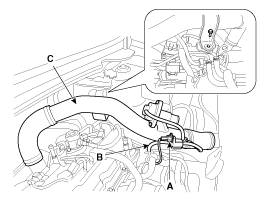
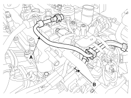
| 4. |
Disconnect the recirculation valve connector (A) and the
vacuum hose (B), and then remove the intercooler inlet pipe & hose
assembly (C).
|
| 5. |
Remove the RH front wheel. |
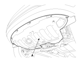
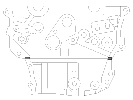
| 6. |
Remove the under cover (A).
|
| 7. |
Turn the crankshaft pulley and align its groove with the
timing mark of the timing chain cover to set the piston of No.1 cylinder
to the top dead center on compression stroke.
|
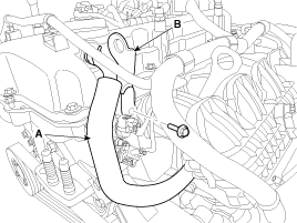
| 8. |
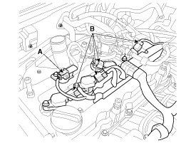
Disconnect the exhaust OCV (Oil control valve) connector (A) and the oxygen sensor connector (B).
|
| 9. |
Disconnect the ignition coil connectors (B) and the fuel pump connector (A), then remove the wiring protector.
|
| 10. |
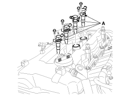
Remove the ignition coils (A).
|
| 11. |
Disconnect the fuel hose (A) and PCSV (Purge control solenoid valve) hose (B).
|
| 12. |
Disconnect PCSV (Purge control solenoid valve) connector (A) and loosen the vacuum pipe assembly mounting bolts and nut.
|
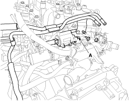
| 13. |
Remove the high pressure pipe (A). (Refer to FL group)
|
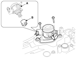
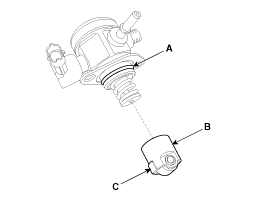
| 14. |
Remove the high pressure fuel pump (A) and the roller tappet (B). (Refer to FL group)
|
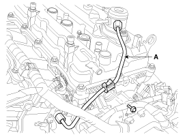
| 15. |
Disconnect the PCV (Positive crankcase ventilation) hose (A) and tnen remove the front engine hanger (B).
|
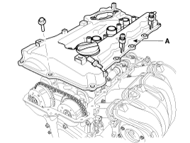
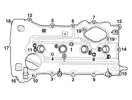
| 16. |
Remove the cylinder head cover (A).
|
| 17. |
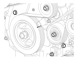
Remove the drive belt (A) after turning the drive belt tensioner (B) counterclockwise.
|
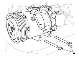
| 18. |
Remove the A/C compressor lower bolts (A).
|
| 19. |
Remove the A/C compressor bracket (A).
|
| 20. |
Drain the engine oil. |
| 21. |
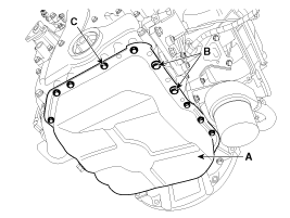
Remove the oil pan (A). Insert the blade of SST (09215-3C000)
between the ladder frame and oil pan. Cut off applied sealer and remove
the lower oil pan.
|
 arrow.
  arrow around more than 2/3 edge of the oil pan, remove it from the ladder frame.
 | 22. |
Set the jack to the edge of ladder frame.
|
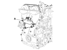
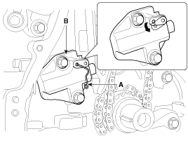
| 23. |
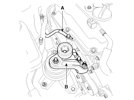
Disconnect the ground line (A), and then remove the engine mounting support bracket (B).
|
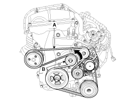
| 24. |
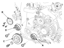
Remove the idler (A), the water pump pulley (B), the crankshaft pulley (C) and the drive belt tensioner pulley (D).
|
| 25. |
Remove the drive belt tensioner (A).
|
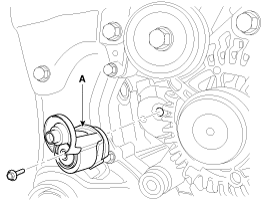
| 26. |
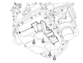
Remove the engine support bracket (A).
|
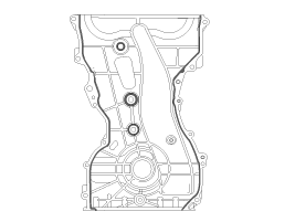
| 27. |
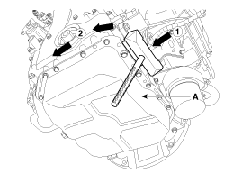
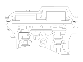
Remove the timing chain cover (A) by gently prying the portions between the cylinder head and cylinder block.
|
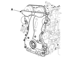
| 28. |
Make sure that the key (A) of crankshaft is aligned with the
mating surface of main bearing cap. As a result of this, the piston of
No.1 cylinder is placed at the top dead center on compression stroke.
|
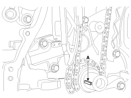
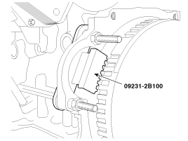
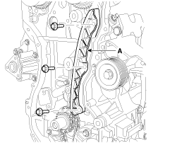
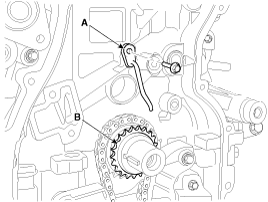
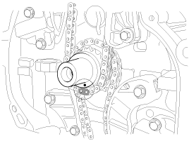
| 29. |
Release the ratchet by pulling the link down using a thin
rod. Compress the piston and then insert a stopper pin (A) into the hole
on the ratchet to hold the compressed piston. Remove the timing chain
tensioner (B).
|
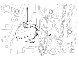
| 30. |
Remove the timing chain tensioner arm (A).
|
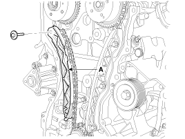
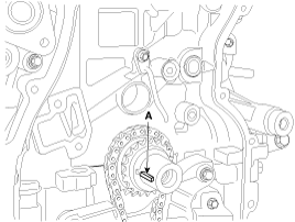
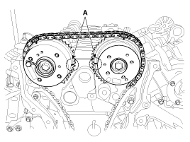
| 31. |
Remove the timing chain (A).
|
| 32. |
Remove the timing chain guide (A).
|
| 33. |
Remove the timing chain oil jet (A) and the crankshaft chain sprocket (B).
|
| 34. |
Remove the balance shaft chain. (Refer to Lubrication system in this group) |
| Inspection |
Sprockets, Chain Tensioner, Chain Guide, Chain Tensioner Arm
| 1. |
Check the camshaft sprocket and crankshaft sprocket for abnormal wear, cracks, or damage. Replace as necessary. |
| 2. |
Inspect the tensioner arm and chain guide for abnormal wear, cracks, or damage. Replace as necessary. |
| 3. |
Check that the tensioner piston moves smoothly when the ratchet pawl is released with thin rod. |
Drive belt, Idler, Pulley
| 1. |
Check the idler for excessive oil leakage, abnormal rotation or vibration. Replace if necessary. |
| 2. |
Check belt for maintenance and abnormal wear of V-ribbed part. Replace if necessary. |
| 3. |
Check the pulleys for vibration in rotation, oil or dust deposit of V-ribbed part. Replace if necessary. |
| Installation |
| 1. |
Install the balance shaft chain. (Refer to Lubrication system in this group) |
| 2. |
Install the crankshaft chain sprocket (B) and the timing chain oil jet (A).
|
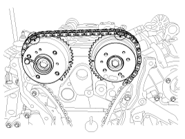
| 3. |
Set the crankshaft so that the key (A) of crankshaft will be
aligned with the mating surface of main bearing cap. Put the intake and
exhaust camshaft assembly so that the TDC marks (B) of the intake and
exhaust CVVT sprockets will be aligned with the top surface of cylinder
head. As a result of this, the piston of No.1 cylinder is placed at the
top dead center on compression stroke.
|
| 4. |
Install the timing chain guide (A).
|
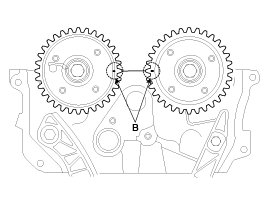
| 5. |
Install the timing chain. To install the timing chain with no slack between each shaft (cam, crank), follow the below procedure.
Crankshaft sprocket (A) > Timing chain guide (B) > Intake CVVT sprocket (C) > Exhaust CVVT sprocket (D).
|
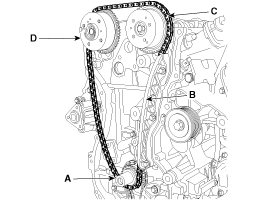
| 6. |
Install the timing chain tensioner arm (A).
|
| 7. |
Install the timing chain auto tensioner (B) and remove the stopper pin (A).
|
| 8. |
After rotating crankshaft 2 revolutions in regular direction
(clockwise viewed from front), confirm that the TDC marks (A) on the
intake and exhaust CVVT sprockets aligned with the top surface of
cylinder head.
|
| 9. |
Install the timing chain cover.
|
| 10. |
Install the engine support bracket (A).
|
| 11. |
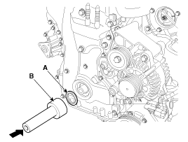
Install the crankshaft front oil seal (A) using SST (09214-3K000, 09231-H1100) (B).
|
| 12. |
Install the drive belt tensioner (A).
|
| 13. |
Install the idler (A), the water pump pulley (B), the crankshaft pulley (C) and the drive belt tensioner pulley (D).
|
| 14. |
Install the engine mounting support bracket (B) and connect the ground line (A).
|
| 15. |
Remove the jack from the ladder frame. |
| 16. |
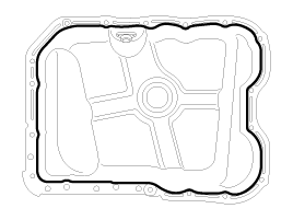
Install the oil pan.
|
| 17. |
Install the A/C compressor bracket (A).
|
| 18. |
Install the A/C compressor lower bolts (A).
|
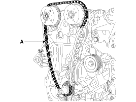
| 19. |
Install the drive belt (A).
Crankshaft pulley > A/C pulley > Alternator pulley >
Idler #1 pulley > Idler #2 pulley > Water pump pulley > Tensioner
pulley.
Rotate the drive belt tensioner arm (B) counterclockwise
moving the tensioner pulley bolt with wrench. After putting the belt on
the tensioner pulley, release the tensioner pulley slowly.
|
| 20. |
Install cylinder head cover.
|
| 21. |
Install the front engine hanger (B) and then connect the PCV (Positive crankcase ventilation) hose (A).
|
| 22. |
Install the high pressure fuel pump (A) and the roller tappet (B). (Refer to FL group)
|
| 23. |
Install the high pressure pipe (A). (Refer to FL group)
|
| 24. |
Connect PCSV (Purge control solenoid valve) connector (A) and tighten the vacuum pipe assembly mounting bolts and nut.
|
| 25. |
Connect the fuel hose (A) and PCSV (Purge control solenoid valve) hose (B).
|
| 26. |
Install the ignition coils (A).
|
| 27. |
Connect the ignition coil connectors (B) and fuel pump connector (A) after installing the wiring protector.
|
| 28. |
Connect the exhaust OCV (Oil control valve) connector (A) and the oxygen sensor connector (B).
|
| 29. |
Install the under cover (A).
|
| 30. |
Install the intercooler inlet pipe & hose assembly (C)
ans then connect the recirculation valve connector (A) and the vacuum
hose (B).
|
| 31. |
Install the RH front wheel. |
| 32. |
Install the air cleaner assembly.
|
| 33. |
Connect the battery negative terminal (A).
|
| 34. |
Install the engine cover. |
| 35. |
Add all the necessary fluids and check for leaks. Connect GDS. Check for codes, note, and clear. Recheck.
|
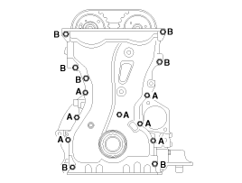
 Timing Chain: Components and Components Location
Components
1. Intake camshaft2. Exhaust camshaft3. Intake CVVT assembly4. Exhaust CVVT assembly5. Timing chain6. Timing chain guide7. Timing chain tensioner arm8. Timing chain tensioner9. Timing ...

Other Information:
ETC (Electronic Throttle Control) System: Specifications
Specification
[Throttle Position Sensor (TPS)]
Throttle Angle(┬░)Output Voltage(V) [Vref = 5.0V]TPS1TPS200.05.0100.484.52200.954.05301.433.57401.903.10502.382.62602.862.14703.331.67803.811.19904 ...
Specifications
Specifications
ItemsBulb Wattage (W)Front(General)Head lamp (High/Low)55/55Front turn signal lamp28Front position lamp8 or LEDFront fog lamp27Turn signal lamp (Door mirror)LEDRearRear stop lamp ( ...
Categories
- Home
- Kia Sportage QL (2015-2019) Owners Manual
- Kia Sportage QL (2015-2019) Service Manual
- Kia Sportage SL 2010-2016 Owners Manual
- Kia Sportage SL 2010-2016 Service Manual

Copyright ® www.kispmanual.com 2014-2026