 Kia Sportage: Heater Unit: Components and Components Location
Third generation SL (2010ŌĆō2016) / Kia Sportage SL Service & Repair Manual / Heating,Ventilation, Air Conditioning / Heater / Heater Unit: Components and Components Location
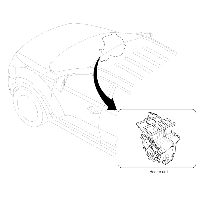
| Component Location |

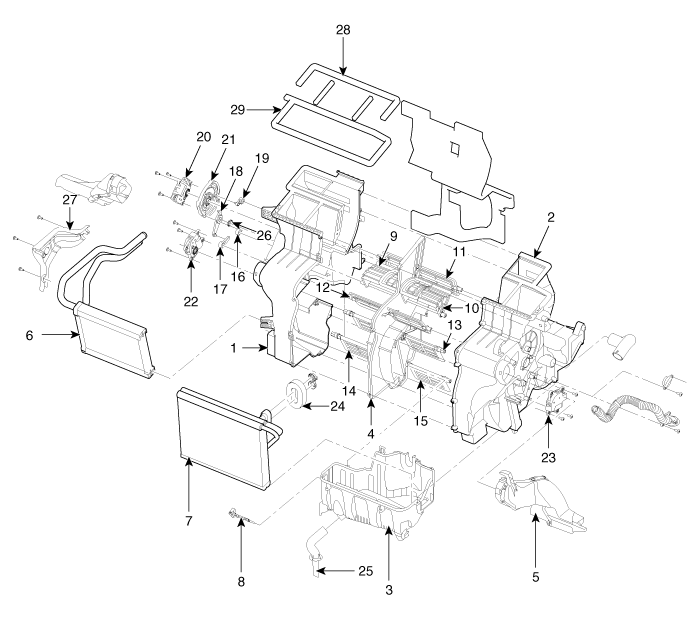
| Components |

| 1. Heater Case (LH) 2. Heater Case (RH) 3. Heater Lower Case 4. Separator 5. Shower Duct 6. Heater Core 7. Evaporator Core 8. Evaporator Sensor 9. Vent Door 10. Vent Door | 11. Def Door 12. Foot Door 13. Temp Control Door 14. Temp Control Door 15. Temp Control. Door 16. Vent Door Arm 17. Foot Lever 18. Foot Door Arm 19. Def Lever 20. Mode Control Actuator | 21. Mode Cam 22. Temp Control Actuator (Dual Climate Control only) 23. Temp Control Actuator 24. Flange Seal 25. Drain Hose 26. Washer Spring 27. Heater Core Cover 28. Flange Seal 29. Flange Seal |
 Heater
...
 Heater Unit: Repair procedures
Replacement
1.
Disconnect the negative (-) battery terminal.
2.
Recover the refrigerant with a recovery/ recycling/ charging station.
3.
When the engine is cool, drain the engine coola ...
Other Information:
Anchor Pretensioner: Description and Operation
Description
Anchor pretensioner operates as well as belt Pretensioner at
the same time If it gets into its deploy condition after a collision. It
is located at near anchor on front seat and it ...
START/RUN
Not illuminated
ŌĆó With automatic transaxle
To start the engine, depress the brake pedal and press the ENGINE START/ STOP
button with the shift lever in the P (Park) or the N (Neutral) position ...
Categories
- Home
- Kia Sportage QL (2015-2019) Owners Manual
- Kia Sportage QL (2015-2019) Service Manual
- Kia Sportage SL 2010-2016 Owners Manual
- Kia Sportage SL 2010-2016 Service Manual
Copyright ® www.kispmanual.com 2014-2026
