 Kia Sportage: Mode selection
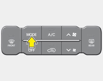
The mode selection button controls the direction of the air flow through the ventilation system.
The air flow outlet port is converted as follows:

Refer to the illustration in the ŌĆ£Manual climate control systemŌĆØ.
Face-Level

Air flow is directed toward the upper body and face. Additionally, each outlet can be controlled to direct the air discharged from the outlet.
Bi-Level

Air flow is directed towards the face and the floor.
Floor-Level

Most of the air flow is directed to the floor, with a small amount of the air being directed to the windshield and side window defrosters.
Floor/Defrost-Level

Most of the air flow is directed to the floor and the windshield with a small amount directed to the side window defrosters.
Defrost-Level
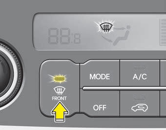
Most of the air flow is directed to the windshield with a small amount of air directed to the side window defrosters.
Instrument panel vents
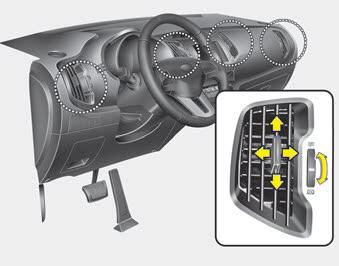
The outlet vents can be opened or closed separately using the thumbwheel. (If equipped)
Also, you can adjust the direction of air delivery from these vents using the vent control lever as shown.
 Manual heating and air conditioning
The heating and cooling system can be controlled manually by pressing buttons
or turning knob(s) other than the AUTO button. In this case, the system works sequentially
according to the order of b ...
 Temperature control
The temperature will increase to the maximum (HI) by turning the knob to the
extreme right.
The temperature will decrease to the minimum (Lo) by turning the knob to the
extreme left.
When turn ...
Other Information:
Oil hydraulic Motor(Actuator): Schematic Diagrams
Circuit Diagram
...
Maintenance under severe usage conditions
The following items must be serviced more frequently on cars normally used under
severe driving conditions. Refer to the chart below for the appropriate maintenance
intervals.
R : Replace
I : I ...
Categories
- Home
- Kia Sportage QL (2015-2019) Owners Manual
- Kia Sportage QL (2015-2019) Service Manual
- Kia Sportage SL 2010-2016 Owners Manual
- Kia Sportage SL 2010-2016 Service Manual
