 Kia Sportage: Rear Hub - Carrier: Repair procedures
Third generation SL (2010ŌĆō2016) / Kia Sportage SL Service & Repair Manual / Driveshaft and axle / Rear Axle Assembly / Rear Hub - Carrier: Repair procedures
| Replacement |
| 1. |
Loosen the wheel nuts slightly. Raise the vehicle, and make sure it is securely supported. |
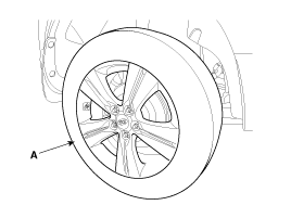
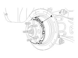
| 2. |
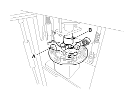
Remove the rear wheel and tire (A) from rear hub.
|

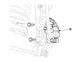
| 3. |
Remove the brake caliper mounting bolts , and then hold the brake caliper assembly (B) with wire.
|
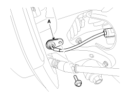
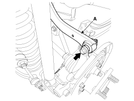
| 4. |
Remove the wheel speed sensor (A), from the knuckle.
|
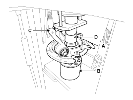
| 5. |
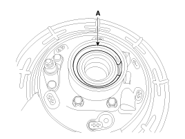
Remove castle nut (A) from the rear hub.
|
| 6. |
Remove the rear brake lining assembly (A).(Refer to BR group - Parking brake system)
|
| 7. |
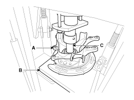
Remove the parking brake cable (B) from the brake shoe (A).
|
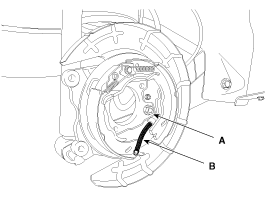
| 8. |
Remove the parking brake cable retaining (B), from the parking brake cable (A).
|
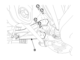
| 9. |
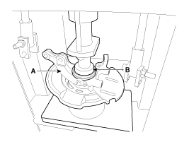
Remove the assist arm (A) from the rear axle carrier.
|
| 10. |
Remove the trailing arm (B) from the rear axle carrier.
|
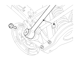
| 11. |
Remove the upper arm (A) from the rear axle carrier.
|
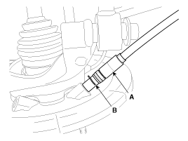
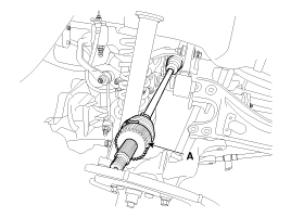
| 12. |
Push the rear axle carrier outward and separate the driveshaft (A) from the axle hub .
|
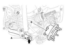
| 13. |
Remove the lower arm (A) from the rear axle carrier(B).
|
| 14. |
Install in the reverse order of removal.
|
| Inspection |
| 1. |
Check the hub for cracks and the splines for wear. |
| 2. |
Check the brake disc for scoring and damage. |
| 3. |
Check the rear axle carrier for cracks |
| 4. |
Check the bearing for cracks or damage. |
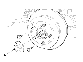
| Disassembly |
| 1. |
Remove the hub assembly form the near knuckle assembly.
|
| 2. |
Using the snap ring pliers, remove the snap ring (A).
|
| 3. |
Remove the hub bearing outer race form the hub assembly.
|
| 4. |
Replace hub bearing with a new one. |
| Reassembly |
| 1. |
Install the hub bearing to the knuckle assembly.
|
| 2. |
Install the hub assembly to the knuckle assembly.
|
| 3. |
Install the snap ring (A).
|
 Rear Hub - Carrier: Components and Components Location
Components
1. Hub cover2. Carrier assembly3. Hub & bearing assembly4. Hub mounting bolt5. Bushing6. Bushing7. Carrier assembly8. Bearing9. Snap ring10. Hub assembly11. Hub bolt12. Bushing
...

Other Information:
Condition and operation in the front passenger occupant detection system
*1) The system judges a person of adult. When a smaller adult sits in the front
passenger seat, the system may recognize him/her as a child depending on his/her
physique and posture.
*2) Do not ...
Folding the outside rearview mirror
Manual type (if equipped)
To fold the outside rearview mirror, grasp the housing of the mirror and then
fold it toward the rear of the vehicle.
Electric type (if equipped)
To fold the outside ...
Categories
- Home
- Kia Sportage QL (2015-2019) Owners Manual
- Kia Sportage QL (2015-2019) Service Manual
- Kia Sportage SL 2010-2016 Owners Manual
- Kia Sportage SL 2010-2016 Service Manual

Copyright ® www.kispmanual.com 2014-2026