 Kia Sportage: ICM (Integrated Circuit Module) Relay Box: Schematic Diagrams
Third generation SL (2010ŌĆō2016) / Kia Sportage SL Service & Repair Manual / Body Electrical System / Fuses And Relays / ICM (Integrated Circuit Module) Relay Box: Schematic Diagrams
| Schematic Diagram |
 ICM (Integrated Circuit Module) Relay Box: Components and Components Location
Component
Pin Information
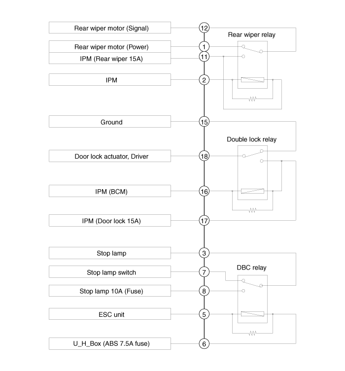
NoConnector ANoConnector A1Rear wiper motor (Power)11IPM (Rear wiper 15A)2IPM12Rear wiper motor (Signal)3Stop lamp13-4-14-5ESC unit15GND6U_H_Box (ABS 7.5A fuse)16IPM (B ...
 ICM (Integrated Circuit Module) Relay Box: Description and Operation
Description
The ICM relay (A) is united with rear wiper relay, and DBC relay which installed inside the lower crash pad. ...
Other Information:
Power Window Motor: Repair procedures
Inspection
Front Power Window Motor
1.
Remove (-) negative battery terminal.
2.
Remove the front door trim.
(Refer to the BD group - "Front door")
3.
Disconnect the connector from the m ...
Schematic Diagrams
Schematic Diagram
...
Categories
- Home
- Kia Sportage QL (2015-2019) Owners Manual
- Kia Sportage QL (2015-2019) Service Manual
- Kia Sportage SL 2010-2016 Owners Manual
- Kia Sportage SL 2010-2016 Service Manual

Copyright ® www.kispmanual.com 2014-2026