 Kia Sportage: TPMS Receiver: Schematic Diagrams
Third generation SL (2010ŌĆō2016) / Kia Sportage SL Service & Repair Manual / Suspension System / Tire Pressure Monitoring System / TPMS Receiver: Schematic Diagrams
| Schematic Diagrams |
| TPMS Receiver Circuit Diagram |
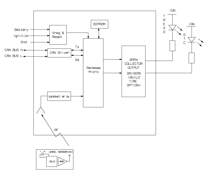
| Harness Connector |

| Pin | Description |
| 1 | Battery |
| 2 | CAN_High |
| 3 | GND |
| 4 | - |
| 5 | - |
| 6 | - |
| 7 | IGN |
| 8 | CAN_Low |
| 9 | - |
| 10 | - |
| 11 | - |
| 12 | - |
 TPMS Receiver: Description and Operation
Description
1.
Mode
(1)
Virgin State
ŌĆó
The receiver as a sole part is shipped in this state. Replacement parts should therefore arrive in this state.
ŌĆó
In this state, there ...
 TPMS Receiver: Repair procedures
Replacement
When the receiver first arrives for replacement:
a.
It will be in Virgin State.
b.
It will not be configured for any specific platform.
c.
It will ...
Other Information:
Direct Electro Hydraulic Actuator Coupling: Components and Components Location
Component Location
1. Automatic transaxle2. Transfer assembly3. Propeller shaft4. Coupling assembly5. Differential assembly
Components
1. Actuator2. Bleed valve3. Flange & Input shaft4. ...
Front Seat: Components and Components Location
Components
1. Headrest2. Headrest guide3. Front seat back cover4. Front seat back heater5. Front seat back pad6. Front seat back power lumbar7. Front seat back duct8. Front seat back frame9. Fron ...
Categories
- Home
- Kia Sportage QL (2015-2019) Owners Manual
- Kia Sportage QL (2015-2019) Service Manual
- Kia Sportage SL 2010-2016 Owners Manual
- Kia Sportage SL 2010-2016 Service Manual

Copyright ® www.kispmanual.com 2014-2026