 Kia Sportage: Repair procedures
Third generation SL (2010ŌĆō2016) / Kia Sportage SL Service & Repair Manual / Body Electrical System / Ignition Switch Assembly / Repair procedures
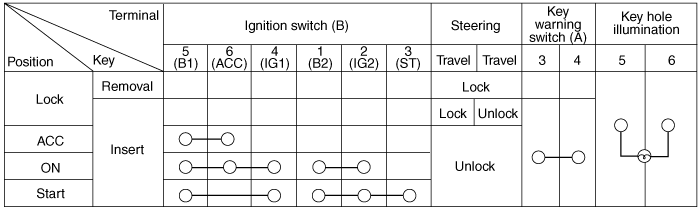
| Inspection |
| 1. |
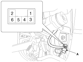
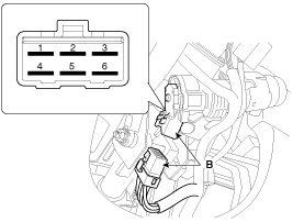
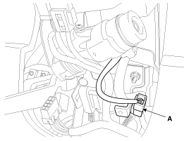
Disconnect the ignition switch connector (B) and key warning switch connector (A) from under the steering column.
|
| 2. |
Check for continuity between the terminals. |
| 3. |
If continuity is not specified, replace the switch. |
| Removal |
| 1. |
Disconnect the negative (-) battery terminal. |
| 2. |
Remove the steering column upper and lower shrouds.
(Refer to the ST group - "Steering column") |
| 3. |
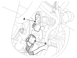
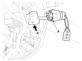
Remove the ignition switch (A) after disconnecting the 6P connector (B).
|
| 4. |
Remove the key warning and immobilizer connector (A).
|
| 5. |
Remove the key illumination cover. |
| 6. |
If it is necessary to remove the key lock cylinder (A), remove the key lock cylinder after pushing lock pin (B) with key ACC.
|
| Installation |
| 1. |
Install the key lock cylinder. |
| 2. |
Install the illumination cover. |
| 3. |
Install the key warning and immobilizer connector. |
| 4. |
Install the ignition switch. |
| 5. |
Install the steering column shrouds and crash pad lower panel. |


Other Information:
Front Strut Assembly: Repair procedures
Replacement
1.
Remove the front wheel & tire.
Tightening torque :
88.3 ~ 107.9N.m (9.0 ~ 11.0kgf.m, 65.1 ~ 79.6lb-ft)
Be careful not to damage to the hub ...
Steering wheel audio controls
Type A
Type B
The steering wheel may incorporate audio control buttons.
✽ NOTICE
Do not operate audio remote control buttons simultaneously.
Driving while distracted is dangerous and s ...
Categories
- Home
- Kia Sportage QL (2015-2019) Owners Manual
- Kia Sportage QL (2015-2019) Service Manual
- Kia Sportage SL 2010-2016 Owners Manual
- Kia Sportage SL 2010-2016 Service Manual

Copyright ® www.kispmanual.com 2014-2026