
 Kia Sportage: Repair procedures
Third generation SL (2010–2016) / Kia Sportage SL Service & Repair Manual / Body Electrical System / Keyless Entry And Burglar Alarm / Repair procedures
| Inspection |
Front Door Lock Actuator Inspection
| 1. |
Remove the front door trim.
(Refer to the BD group - "Front door") |
| 2. |
Remove the front door module. |
| 3. |
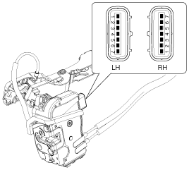
Disconnect the 7P connector from the actuator.
|
| 4. |
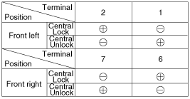
Check actuator operation by connecting power and ground
according to the table. To prevent damage to the actuator, apply battery
voltage only momentarily.
[Central Lock]
|
Rear Door Lock Actuator Inspection
| 1. |
Remove the rear door trim.
(Refer to the BD group - "Rear door") |
| 2. |
Remove the rear door module. |
| 3. |
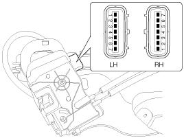
Disconnect the 7P connector from the actuator.
|
| 4. |
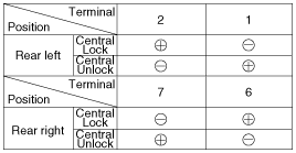
Check actuator operation by connecting power and ground
according to the table. To prevent damage to the actuator, apply battery
voltage only momentarily.
[Central Lock]
|
Tailgate Release Actuator Inspection
| 1. |
Remove the tailgate trim panel.
(Refer to the BD group - "Trunk lid") |
| 2. |
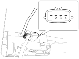
Disconnect the 4P connector from the actuator.
|
| 3. |
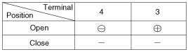
Check actuator operation by connecting power and ground
according to the table. To prevent damage to the actuator, apply battery
voltage only momentarily.
|
Front Door Lock Switch Inspection
| 1. |
Remove the front door trim panel.
(Refer to the BD group - "Front door") |
| 2. |
Remove the front door module. |
| 3. |
Disconnect the 7P connector from the actuator.
|
| 4. |
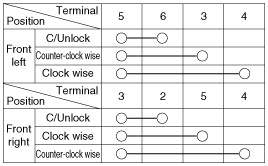
Check for continuity between the terminals in each switch position when inserting the key into the door according to the table.
[Central Lock]
|
Rear Door Lock Switch Inspection
| 1. |
Remove the rear door trim panel.
(Refer to the BD group - "Rear door") |
| 2. |
Remove the rear door module. |
| 3. |
Disconnect the 7P connector from the actuator.
|
| 4. |
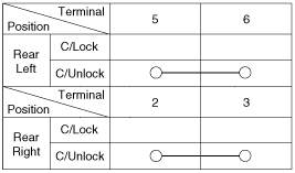
Check for continuity between the terminals in each switch position according to the table.
[Central Lock]
|
Tailgate Lid Open Switch Inspection
| 1. |
Remove the tailgate lid trim.
(Refer to the BD group - "Tailgate") |
| 2. |
Disconnect the 4P connector from the actuator.
|
| 3. |
Check for continuity between the terminals in each switch position according to the table.
|
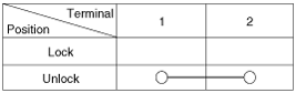
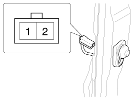
Door Switch Inspection
Remove the door switch and check for continuity between the terminals.
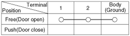
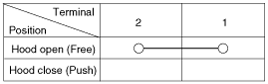
Hood Switch Inspection
| 1. |
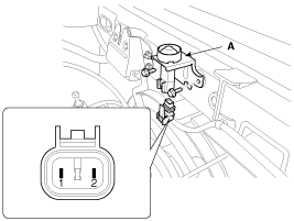
Disconnect the connector from the hood switch (A).
|
| 2. |
Check for continuity between the terminals and ground according to the table.
|
Burglar Horn Inspection
| 1. |
Remove the burglar horn (A) after removing 1 bolt and disconnect the 2P connector from the burglar horn.
|
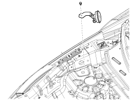
| 2. |
Test the burglar horn by connecting battery power to the terminal 1 and ground the terminal 2. |
| 3. |
The burglar horn should make a sound. If the burglar horn fails to make a sound replace it. |
 Description and Operation
Description
Remote Keyless Entry System
The described function is a radio-frequency remote control
for central doors locking / unlocking, trunk release and Panic activity
of an automotive vehi ...
 Transmitter: Repair procedures
Inspection
1.
Check that the red light flickers when the door lock or unlock button is pressed on the transmitter.
2.
Remove the battery (A) and check voltage if the red light doesn''t flicker ...
Other Information:
Air bag non-inflation conditions
• In certain low-speed collisions the air bags may not deploy. The air bags are
designed not to deploy in such cases because they may not provide benefits beyond
the protection of the seat bel ...
Power Window Switch: Components and Components Location
Components
Power Window Main Switch
Passenger Power Window Switch
Rear Power Window Switch
...
Categories
- Home
- Kia Sportage QL (2015-2019) Owners Manual
- Kia Sportage QL (2015-2019) Service Manual
- Kia Sportage SL 2010-2016 Owners Manual
- Kia Sportage SL 2010-2016 Service Manual

Copyright © www.kispmanual.com 2014-2026