 Kia Sportage: 4WD ECU: Schematic Diagrams
Third generation SL (2010ŌĆō2016) / Kia Sportage SL Service & Repair Manual / 4 Wheel Drive (4WD) System / 4WD Control System / 4WD ECU: Schematic Diagrams
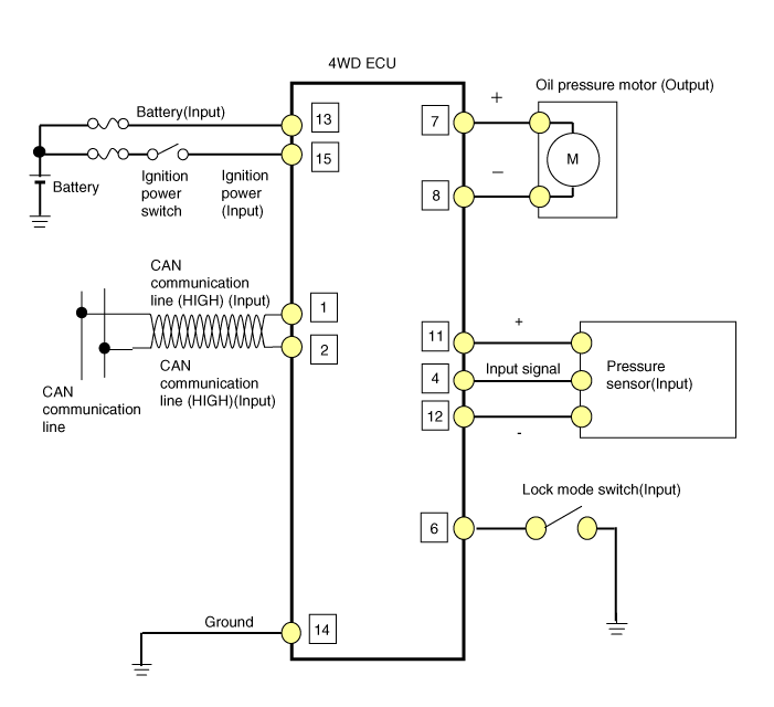
| Circuit Diagram |
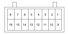
| 4WD ECU Connector |

| Pin | Function |
| 1 | Oil pressure motor A |
| 2 | Oil pressure motor B |
| 3 | Lock mode switch |
| 4 | - |
| 5 | Input sensor signal(+) |
| 6 | - |
| 7 | CAN communication line (High) |
| 8 | CAN communication line (Low) |
| 9 | - |
| 10 | - |
| 11 | - |
| 12 | IG power |
| 13 | Ground |
| 14 | Battery power |
| 15 | Input sensor signal(-) |
| 16 | Pressure sensor(Input) |
| 17 | - |
| 18 | - |
| 4WD ECU Circuit Diagram |

 4WD ECU: Flow Diagram
Power Flow Diagram
4WD ECU Input&Output Diagram
...
 4WD ECU: Components and Components Location
Component Location
1. Crash pad2. Crash lower panel3. 4WD ECU
...
Other Information:
Power Door Mirror Switch: Schematic Diagrams
Circuit Diagram
...
PDM Relay Box: Description and Operation
Description
The PDM relay (A) is united with IG1, IG2 and ACC relays and installed in the lower center fascia panel. ...
Categories
- Home
- Kia Sportage QL (2015-2019) Owners Manual
- Kia Sportage QL (2015-2019) Service Manual
- Kia Sportage SL 2010-2016 Owners Manual
- Kia Sportage SL 2010-2016 Service Manual
Copyright ® www.kispmanual.com 2014-2026
